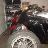
JB4XX Posted July 23, 2009 Author Share Posted July 23, 2009 Could you post pics of the crank trigger? Just like to see where it`s at. Couldnt get the camera to focus on the timing marks. I will be pulling the crank trigger tomorrow and swapping it out. Glad I got the FI light to go out. Quote Link to comment Share on other sites More sharing options...
cbrxxquad Posted July 23, 2009 Share Posted July 23, 2009 Could you post pics of the crank trigger? Just like to see where it`s at. page 17-8 in the manual Quote Link to comment Share on other sites More sharing options...
JB4XX Posted July 23, 2009 Author Share Posted July 23, 2009 I have the 1-4 coil on the right side. Just checking...the coils each have a black wire running to them, they go to the black connector on the coil right? Quote Link to comment Share on other sites More sharing options...
cbrxxquad Posted July 23, 2009 Share Posted July 23, 2009 How in the hell if the crank and cams are in correct position "cams are 180 off".My brain hurts trying to understand that. Cam pulse generator is there so ECU knows when to fire injectors,as long as trigger wheel is installed correctly on EX cam sprocket who cares whether you spin crank 360,720,etc. They are either installed correctly or not .Period. I hope what I was writing when you posted this explains what the diference is. A better way to say it is they are upsidedown from correct....its the #1 ad #4 thing Hell the only thing that tell anything to the compter is the one odd pointer on the exhaust cam pulser wheel, every thing else is even but that. I have the 1-4 coil on the right side. Just checking...the coils each have a black wire running to them, they go to the black connector on the coil right? 1/4 is the yellow blue side,,still looking for your answer Quote Link to comment Share on other sites More sharing options...
cbrxxquad Posted July 23, 2009 Share Posted July 23, 2009 book does not say, but shows the + is the inside one next to the airbox on the right 1/4 coil. and is yellow/blue are you sure the yellow blue is on the right side??? Quote Link to comment Share on other sites More sharing options...
JB4XX Posted July 23, 2009 Author Share Posted July 23, 2009 book does not say, but shows the + is the inside one next to the airbox on the right 1/4 coil. and is yellow/blue are you sure the yellow blue is on the right side??? Yes it's on the right side. Thanks for your help and phone calls everyone! Quote Link to comment Share on other sites More sharing options...
cbrxxquad Posted July 23, 2009 Share Posted July 23, 2009 book does not say, but shows the + is the inside one next to the airbox on the right 1/4 coil. and is yellow/blue are you sure the yellow blue is on the right side??? Yes it's on the right side. Thanks for your help and phone calls everyone! go to bed!!! Quote Link to comment Share on other sites More sharing options...
JB4XX Posted July 23, 2009 Author Share Posted July 23, 2009 Going to sleep on it. Still something I can do look at cam timing? When I talked to Redbird, he described what happened to his exactly like mine is running. I'll try to rule out any other gremlins, then start over with the Cams. Quote Link to comment Share on other sites More sharing options...
HANKSXXX Posted July 23, 2009 Share Posted July 23, 2009 Josh, were the cam sprockets removed at any time or were the cams/sprockets removed and reinstalled as a set? Quote Link to comment Share on other sites More sharing options...
tomek Posted July 23, 2009 Share Posted July 23, 2009 This is easy to do because they are doing the same thing and the diagram looks like your looking at the lobes next to the sprokett on the cam. But, that is the #4 hole. #1 is on the other end. That is why I said they,cams and the trigger wheel are either installed correctly or not. Looking at the latest set of pics, cams seems to be in the right position. Quote Link to comment Share on other sites More sharing options...
Redbird Posted July 23, 2009 Share Posted July 23, 2009 How in the hell if the crank and cams are in correct position "cams are 180 off".My brain hurts trying to understand that. Mine too, and it gave me fits for one evening over three years ago, but rotating it solved my problem. Nothing else was changed. Why does the manual specify TCD on the compression stroke rather than simply TDC? Obviously not Josh's problem, but it was mine, and others here. There's a sensor or some such crap somewhere else. I don't understand all the intricacies of the ECM and FI, or I'd try to explain. Quote Link to comment Share on other sites More sharing options...
JB4XX Posted July 23, 2009 Author Share Posted July 23, 2009 Josh, were the cam sprockets removed at any time or were the cams/sprockets removed and reinstalled as a set? No and yes. Quote Link to comment Share on other sites More sharing options...
JB4XX Posted July 23, 2009 Author Share Posted July 23, 2009 I'll do the crank sensor tonight. If that doesnt work, I will start over. Not sure how to determine if it is TDC compression now that the cams have been out and placed back in LIKE it was TDC compression. My neighbor wandered over to the garage last night and asked why I just didnt take it to the dealer to fix it now. Quote Link to comment Share on other sites More sharing options...
cbrxxquad Posted July 23, 2009 Share Posted July 23, 2009 If you look at page 8-23 in the manual, there are three pictures that matter. They are not on the same page. #1 How to install the sprockets on the cams and the cam pulse generator rotor. How they align to the #1 lobes. If you align to the #4 lobes instead of the #1, it will do what Joshs does, as well as mine and Deans did. It is easy to do as the only place to know which is 1 or four is the valvecover. When I made the mistake, I painted the numbers yellow on my valve cover. This is not the mistake I did, just so you know, it is one that can be done and get the same reaction. I don't think many would do this mistake as most would not take the sprockets off the cams or the cam pulse generator rotor. (Joe, on our cam project, I wonder if an other CPGR could be made that has four arms to correct this problem with it working on a efi engine? I don't think we can get the ecm to work though. Otherwise it will only work on a carb bird.) #2 Next picture, tell you to turn the engine to TDC, not compression #1. This is all that matters. ( I think that most are getting lost in that one turn of the crank is half a turn of the cam, hence cams off 180 and at that point #4 fires, not #1. but, since the odd pointer has not made the second pulse close to the two that are 180 apart the ecm don't know when to fire the fuel sequence that starts with #1. The odd pointer starts the fuel sequence of first one injector, followed by the firing order injector next. I think the firing order is 1423, and the injectors fire in that order. So it is the indicator on the CPGR that sets up the order that is off where it should inject fuel on degree of crank rotation. #3 Next is the picture at the bottom of 8-24 on installing the cam chain on the sprockets and the locating marks on the sprockets. It needs to be understood that Josh has all this right. and has a results that is like having them wrong. You can see on his ex cam that the CPGR is aligned with the EX on the sprocket, and the picture of the cam lobes on #1 is correct. Now wither it is at TDC or not we got to trust him. Quote Link to comment Share on other sites More sharing options...
tomek Posted July 23, 2009 Share Posted July 23, 2009 How in the hell if the crank and cams are in correct position "cams are 180 off".My brain hurts trying to understand that. Mine too, and it gave me fits for one evening over three years ago, but rotating it solved my problem. Nothing else was changed. Why does the manual specify TCD on the compression stroke rather than simply TDC? Obviously not Josh's problem, but it was mine, and others here. There's a sensor or some such crap somewhere else. I don't understand all the intricacies of the ECM and FI, or I'd try to explain. Somewhere, somehow, that f'n ECM knows which is which rotation and only sprays fuel at the 60 degrees off TDC intake stroke. There is no wasted fuel design... Yea,but that is precisely why cam pulse generator with trigger wheel,etc is there on FI bikes,so ECU can recognize whether cylinder is on compression or exhaust stroke .Whether the crank is on compression or exhaust stroke is determined by the position of camshafts. So, if crank,cams and trigger wheel are in correct position it does not matter how many times you spin crank prior or after,it still be on compression stroke.. BTW ,you can take injector duty cycle to something ridiculous like 85%,heck even 100% but they would burn out quickly.Normally they are about at 60 % at WOT.My point is they start spraying not only when the inlet valve is open,but even before it , for sure not at 60 deg ATDC.You wanna start that rather sooner then later to improve atomization. I`m pretty sure XX has sequential FI system,but there are batch fire race car systems that spray all injectors as one every crankshaft revolution,and the engine still f. runs.My point is with FI,unlike ignition,when you fire injectors is not that crucial,you`d be wasting fuel at light loads,but the motor would still run. It is Otto cycle without direct injection, not Diesel. I might go to he Autobahn,Sunday,right ? Quote Link to comment Share on other sites More sharing options...
cbrxxquad Posted July 23, 2009 Share Posted July 23, 2009 this page shows what correct CPGR looks like in the second from the last picture, and 180 off CPGR in the last picture this page shows how to put the CPGR on the exhaust cam in the first picture. How to align the crank in the second picture And how to align the cams in the last picture and in this picture the drawing in the middle is where I made my mistake, it shows the cam lobes for #1 and where they should be, I was mistaken in thinking that they were on the sprocket end instead of the opposite end of the cam...Yes I put the sprockets on wrong. I hope this clears it up... I am going to shoot a picture of the crank trigger for info. Quote Link to comment Share on other sites More sharing options...
Redbird Posted July 23, 2009 Share Posted July 23, 2009 I might go to he Autobahn,Sunday,right ? Yeah, I'll be there on the 2nd. Quote Link to comment Share on other sites More sharing options...
cbrxxquad Posted July 23, 2009 Share Posted July 23, 2009 How in the hell if the crank and cams are in correct position "cams are 180 off".My brain hurts trying to understand that. Mine too, and it gave me fits for one evening over three years ago, but rotating it solved my problem. Nothing else was changed. Why does the manual specify TCD on the compression stroke rather than simply TDC? Obviously not Josh's problem, but it was mine, and others here. There's a sensor or some such crap somewhere else. I don't understand all the intricacies of the ECM and FI, or I'd try to explain. did you take the sprokets off the cams. Cause I bet if you did yours is like mine was, and flipping the cams made it run on four not 1. I wonder now. Can't prove it though In other words, you could put the sprockets on with #4 lobes up and it would work with the cams upsidedown. I chose to change the sprockets to the correct way, and it worked. Yeah, I pulled it all apart to do it or it would have bent valves. Quote Link to comment Share on other sites More sharing options...
cbrxxquad Posted July 23, 2009 Share Posted July 23, 2009 good enough Quote Link to comment Share on other sites More sharing options...
Redbird Posted July 23, 2009 Share Posted July 23, 2009 Sprockets were never removed from the cams, nor was the CPGR. I dunno, man. It honestly doesn't make sense to me either, but there you go... Quote Link to comment Share on other sites More sharing options...
jon haney Posted July 23, 2009 Share Posted July 23, 2009 Stan, that firing order doesn't sound quite right for an inline 4. Think about it. It would have to be 1-3-4-2 or 1-2-4-3. I thought cam sprocket bolts were a few degrees from being 180 apart so that they would only go on one way? I guess you could put them on inside-out. Is that possible? Quote Link to comment Share on other sites More sharing options...
cbrxxquad Posted July 23, 2009 Share Posted July 23, 2009 yeah, i was guessing, good catch Quote Link to comment Share on other sites More sharing options...
cbrxxquad Posted July 23, 2009 Share Posted July 23, 2009 yeah, i was guessing, good catch it has to be 1342 or 1243 but I cant find it. sorry. Stan, that firing order doesn't sound quite right for an inline 4. Think about it. It would have to be 1-3-4-2 or 1-2-4-3. I thought cam sprocket bolts were a few degrees from being 180 apart so that they would only go on one way? I guess you could put them on inside-out. Is that possible? I am pretty sure 180 apart, cause I remember installing wrong. That and the instructions tell how to do it right. Quote Link to comment Share on other sites More sharing options...
mikesail Posted July 23, 2009 Share Posted July 23, 2009 Yea,but that is precisely why cam pulse generator with trigger wheel,etc is there on FI bikes,so ECU can recognize whether cylinder is on compression or exhaust stroke .Whether the crank is on compression or exhaust stroke is determined by the position of camshafts. So, if crank,cams and trigger wheel are in correct position it does not matter how many times you spin crank prior or after,it still be on compression stroke.. Correct, and after looking more closely at the cam position trigger, you can see that there is 1 prong that is not 180 degrees off of the other, that's how it knows. So, we had the cams in the correct position in the first place. There is an electronic issue here -- crimped wire, bad connection, bad sensor, etc. The sensor on the crank is a hall effect sensor and those are VERY sensitive to contact, so even turning the crank backward or a slight bump might wreck it. Dean, you are missing what is happening for the cam trigger. Honda is doing something funny, a single pulse from the cam trigger is all you need for unambiguous timing. The extra two fingers are special for some unknown reason. If the exhaust cam is not set correctly on the cam sprocket (i.e. turned 180 ) , then the valves will still clear but you will have a really screwed engine with the exhaust opening at the same time as ignition occurs, more or less. Looking at the cam sprocket without seeing the lobes I cannot tell what the cam timing is. You need to turn the engine over and verify that the intake is opening just as the exhaust is closing, if not the cam is mismounted. You can check any cylinder, they will all be the same. If the cam sequence is correct, then it is necessary to check the phase of the cam trigger, since it is not symmetrical for some unknown reason. I think Stan was trying to say that the pic in the manual is misleading, need to know which lobe they are referring to. Close. At 50% duty cycle at a high RPM is the most wear on an injector. Higher duty cycle means it is open longer and closed less. RPM is the biggest factor as to how often it has to open the valve or not. I have run high quality Bosch injectors to 13,500 RPM and seen inconsistencies in fuel delivery. These high impedance injectors are not as well designed as the low impedance peak-hold variety. There are some now hitting the market that are supposed to be better, but to get a low impedance driver, you have to change ECU to one of the higher end ones. (Not a DTA, for example, more likely an Accel or MoTeC..) RPM is the ONLY factor that determines how often the injector valve opens, right? I`m pretty sure XX has sequential FI systemIt absolutely does have sequential for fuel economy and driveability at a lower RPM with partial throttle positions. There is no other reason for a cam position sensor and the complexities it offers but the EPA does care about wasted fuel and emissions. Uh, there is another reason. Unless you have a distributor for the spark, you have to have a cam sensor to decide how to "distribute" the coil primary voltage. Anyway, I digress.. If all the mechanical cam information lines up, we move onto electronic troubleshooting. Once you have swapped out the cam and crank pickups to known working versions and retested (make sure you didn't accidentally fix it along the way), it is time to move on to electrical diagnosis. Time to check the cam trigger all the way back to the ECM and the cam position trigger all the way back to the ECM. You'll need a wiring diagram for the harness, disconnect the PC (2? 3?), and do some continuity testing with a meter, not an idiot light. Wiggle the wires and see if you can get a partial/limited/weak connection at each test. Welcome to the turbo bike hobby, Josh... I agree, though it appears that the ECU will know if the trigger is inoperative. Quote Link to comment Share on other sites More sharing options...
cbrxxquad Posted July 23, 2009 Share Posted July 23, 2009 Josh posted a picture of the cam lobes on #1 and the exhaust is correct. post 47 Quote Link to comment Share on other sites More sharing options...
Recommended Posts
Join the conversation
You can post now and register later. If you have an account, sign in now to post with your account.