

ActionStarCBRxx
-
Posts
690 -
Joined
-
Last visited
Content Type
Profiles
Forums
Gallery
Events
Everything posted by ActionStarCBRxx
-
I was curious about the pretty green of the Honda fluid and wondered why it was so "special". So I am resurecting this thread for others to see.
-
Thanks Zero... It goes back together just fine and everything is a tight fit. Its just odd that there is a 10x50 collar that pushes the bolt out that much further. I put the radiator in and out two or three times thinking it was odd. So it was a waste of time because I kept questioning myself. The part numbers are 20 and 24.
-
I never noticed this before... I am took the radiator off to straighten out the fins and clear out the mini rock debris (along with changing out all the hoses and thermostat). Its been about a month now and I wasnt sure how it went back together. The book isnt much help in showing the diminsions... so I looked at RonAyers site and they show the collar sticking out (way out) of where the bolt actually tightens down. Why is that?? How does it affectively support the radiator with such a long extension? Link to RonAyers http://www.ronayers.com/RADIATOR-C183134.aspx part number 20/24. Linky To RonAyers.com Thanks! Kelly
-
Excellent Thanks! Is there a trick to getting the brushes back on? I was tempted to undo the coiled springs... but then I was worried I would never get it back on. The brushes are a bugger to get all four on at the same time. I worked on them for an hour at the kitchen table before giving up.
-
Thank you gentleman for the ideas. I apologize for not replying sooner... but I havent had much time to work on the bike. I unplugged everything as suggested and execpt for the starter and it was still blowing the main fuse. I took the starter off and found that there was continuity between the brush post (where the cable connects) and the outer cover. I went ahead and ordered another starter at this point from ebay. That starter arrived and it too showed continuity between the post and the outer cover. So I took my starter apart and found that the brushes that connect to the c shaped thing are 3.5mm. The book states that the service level are 4.5mm. Also the rubber that is the first layer between the brush terminal post and the outer case was worn and brittle. So that explains the continuity between the post and the case. I did not have any ugly burn marks on the commutaror bars and there was no continuity from the commutaror bars to the the armature shaft. So it looks like the shaft is still good. The question now is the starter rebuildable by replacing the rubber/insulaters/washers on the brush terminal post and replacing the four brushes? Thanks! Kelly
-
A few months back my bike burned up the connectors to the main fuse. I decided to replace the wire harness and take care of several issues at once that I had neglected. (Oil/ dash lights and back dash/ CCT / Tyres). I did replace the main fuse/Solenoid when I did the wire-harness as well. So there are no cuts in this harness. I decided to replace the wiring harness to make sure I had a clean start. I finally got the new harness in but the bike still blows the main fuse as soon as I turn the key to the on position. I do know that the ignition is always defaulted to on and the kick stand was down. I have only attempted turn the bike on the one time since the issue started a few months back. I did a brief look at the manual and there is a reference to all the components that are in that starting loop. IF I read it correctly it was the ignition switch, the kickstand and the starter (I dont recall if the fuel pump was in that loop?). So I know I need to grab the voltmeter and go to work there. Is it possible that when the plug burned that some other component was shorted and is causing this? Which would be the most likely culprit to start with? Correct me if I am wrong... but is whats happening is that something that is hot is either touching a ground, or a relay/component is allowing electricity to pass across wires that should be grounded? So what I would see when testing continuity (without power to battery) is a situation where there should be continuity but it wont be there or the opposite, there should not be continuity but there is?
-
I was going to say Harbor Freight Press... the 12 ton for $99. But I don't know if the tire/wheel will fit between the two side bars? I have that one and use it quite a bit... but I haven't tried to put a motorcycle rim/tire in there.
-
Internet Parts Dealer Recomendation
ActionStarCBRxx replied to ActionStarCBRxx's topic in The Garage
PM Sent with small parts list for 97. -
Can you all reply back with a few dealers that you have had good experience with and parts that are good price? Looking for original blackbird parts like starter solenoid, cooling system and dash parts. I like Ron Ayers for their micro fiche but their parts always seem as high as local dealers here. I used to buy a lot of parts from Zanotti Motors but I haven't had a response from them in three days. I have a grocery list of part numbers from the micro fiche, but I need a dealer to double check the numbers... as some of the parts I want have three part numbers for the same part description. Then I need them to place the order for me. So I need some human intervention from the dealership. Thanks! Kelly
-
WD-40 has always been my go to for almost everything on the bike. There is a lot of talk about WD-40 washing out the oil in the X/O rings since its a penetrating fluid. So I thought I would give diesel a try. On the chain and sprocket area the diesel really made wiping the nasty build up super easy. I was really surprised that it worked so well on the under tail! I plan on soaking the chain for a few days in the heavy 80/90 gear oil.
-
I know that there are two camps here... the camp that cleans the bike meticulously and the other camp that believes grime and dirt build character! :icon_silenced: A buddy of mine that rides dirt bikes was always a believer in using diesel to clean bikes (chains sprockets grim dirt etc) I have never used diesel until tonight. Normally I use Honda polish or Plexus to clean the bike. Rarely do I ever use water (unless it rains). I fall in the meticulous camp... either my bike is really clean or super busy because I am behind on maintenance and haven't had time to fix/clean. This week I burnt the main fuse which basically put the bike down. So now I start my grocery list of maintenance on the bike that I have neglected for the past 6 months. Tires/oil/CCT/dash lights etc. I really hate working on a dirty bike so I usually clean everything as I go along. This time since I have been riding the bike more in the adverse weather (cold/snow/rain/hot sun) the bike is really dirty. Since the tires on my list, then I usually break the chain and soak it in 80/90 oil. This time the chain was just nasty. The front sprocket had a perfect mixture for lapping values (dirt and grease in a fine thick powder!)... so I broke out the diesel and soaked the chain in it. The dirt and grime literally falls off. I decide to put some diesel on a rag and wipe down the under tail. The nastyness that your tire flips up into the under tail... the diesel just wiped the dirt off!! Then I used the rag and cleaned out around the front sprocket and all that dirt wiped off!! I mean it just wipes off and falls in a clump on the floor! WOW. After I wiped everything off I went back with Honda Polish and wiped the diesel off everything! WOW like showroom clean! Is there any ill side effects of using diesel on the bike and following up with a cleaning polish like Honda Polish or Plexus? Any reason why you couldn't put that stuff in a spray bottle and use it in the engine compartment of a car or truck to get all the road grime off? It looks like its safe on rubber since fuel lines on my diesel truck are rubber? Any thoughts?
-
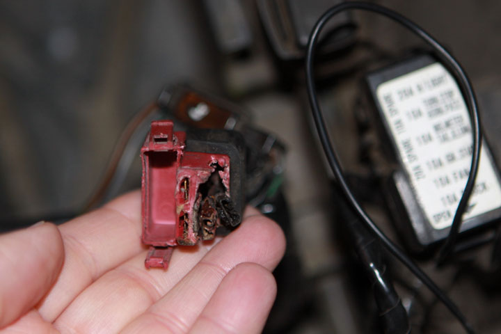
I should have specified I had a 97. It has a red cap/top on it. It's the fusable link between the battery and the starter. In the link to RonAyers its would be where the 20 amp fuse for #27 goes. I think there are six wires total... two in the bottom part of the plug and four in the top half? I don't have it in front of me. I will have my wife send me a picture and I will post it.
-
I have a short somewhere on my bike. It fried my master fuse link. In order to get at the fuse I had to use a screw driver to pry apart the connectors (top cap with fuse from bottom). Since it was semi melted and brittle I ruined the top/cap/lid and the plastic separating the four wires. I don't see this part separate in the micro fiche at Ron Ayers.com. It looks like they want you to buy the whole wiring harness. RonAyers.com I know I can buy a new wiring harness from the dealer, or a used one from ebay for half the price. Do you think if I had enough of a short to cook the master fuse that I should be worrying about the wire integrity and should opt for a new harness? Or would a used harness work or just buy a used and cut the master fuse off and wire it in place using soldier? Does anyone have a butchered harness here on the CBR forum that still has the master fuse? I don't know the cause of the short yet. I suspect it may be the dash lights as they have been blinking on and off for a month now and finally no longer come on. I pulled the fairings yesterday after work and will start trying to hunt down the cause. Edit for picture of master fuse Thanks! Kelly
-
Just an FYI... Motorcycle Superstore (motorcycle-superstore.com) has a sale on the Bridgestone Tires - 43% off. Discount code is M71-Bridgestone-5 Also included in that is free shipping. So I just picked up a pair of BT-023 Battlax Sport Touring tires. I have always run Michelin's PP's. I don't get but a year out of them! It will be good to see how these run.
-
+1 early set, maybe two years since bought. If you want, I will open and shoot some pictures, but only if you want it.. Thanks Stan... I am going to pass. I would rather go back with the factory Honda parts. I don't have the patience and I would mess this up trying to get the fit to be perfect. I apologize... I thought this was genuine Honda. Kelly
-
WTB Rear Brake Caliper
ActionStarCBRxx replied to ActionStarCBRxx's topic in The Sales Floor -- For Sale/Wanted
Sounds Good. How do you want me to send payment? -
PM sent.
-
Greetings! I am looking to buy a rear brake caliper. My bike is a 1997 blackbird. If you have one or a lead on one, please let me know! Thanks! Kelly
-
I second this advice. 3rd the advice.
-
Stan, Is this the European set or another set? Is it all the pieces? (tank/tail/left/right/nose) I am interested. I was going to PM you today to ask about European set... what a coincidence! Please give me first dibs as we work a price. *Edit* I have the 1997 bird... will this fit mine? Thanks! Kelly
-
I thought I had replaced my tires last year on my daily driven 97 bird. I got a nail through the rear and while pulling the tires, I saw that the front was down to the little tread marker. So I am getting two new Pilot Powers put on. I cant recall if I bought the Pilot Powers or the Pilot CT's last round. Regardless I drive about 150 miles a week. That would be me about 7200 for the year (assuming 48 weeks) And this is my daily driver... so I rode in the snow in the winter, the rain, and the heat. So the question is... does high heat (100+) play a factor in wearing down the tires while driving? Or should I be happy with the 7000 miles I got out of them? The other odd thing I noticed that I was closer to the edge on the rears than I was on the fronts. Is that normal or just a sign of spazzy riding?
-
WD-40 works great for cleaning the oil off the pan and bolt as well!
-
+1 on the oil and cleaning the clutch rod. I make this part of my regular yearly maintenance. I hate bad shifts. Pull the rod all the way out and re-lube the end of it. I even wire wheel it to make it clean again.
-
Are you F'N Kidding me? I just got around to replacing mine with the Balls. Please put me down for a replacement set for a Non FI bird... 1997 the original. We have enough to get a group buy going and get a deal?
-
Here is my writeup on installing the Datel Volt Meter. I will attach pictures this evening... Wiring the Datel DC Voltmeter (Link to Datel - http://www.datelmeters.com/cgi-bin/webshop...t-dcvoltmeters) Datel Meters Have A Plan The first step is to have a plan of attack. Know where you want to put Datel voltmeter. Know what wires your going to tie into to get power. Know what you’re going to ground to. Don’t just start pulling the fairings and wing it… your bike will be down for days instead of hours, and you will be making several trips to the parts store. I started out without a plan and the dang project took three days! If I had to do it all over, my plan would be this. 1) I know I want to mount the Datel voltmeter in the flat spot right where the left/right plastic cover to the speedo bezel is. (#15 on the Ron Ayers micro fiche for upper cowel) 2) I know I need to make the connections so that it can come lose easily without pulling the wires off the Datel voltgauge 3) I know I want to tie into the factory wiring at the fuse connection. I would like to use the horn or lights as my tie in. 4) I want to tie my ground either to the back of the bike on the swing arm, or the factor ground where the battery ties. 5) I know the distance from the front to the rear is basically five to six feet… so I need that much wiring. 6) I know I want it to look factory stock, so I will need a wire loom, and black electrical tape 7) I know I want to solder as many connections as possible so I need to find connectors that allow me to solder or don’t have the protective plastic covering that makes the connection un-solderable. Create A List of Supplies So based on my requirements from my list I now need to gather supplies. I purchased the 3½ Digit RED LED (DMS-20PC-0-DCM) volt guage. The front of gauge is water resistant. I also bought the Mounting Bezel for all DMS-20 series meters (DMS-BZL3-C). Ok so that takes care of the meter. Now the wiring… I choose to go with red wire for the positive (+) and black for the negative (-). I could have used green for the negative, as that is what Honda seems to use on their diagram. I bought two 30 ft rolls of 18-gauge wire (red & black). I bought two five-foot sections of 3/8 wire loom. If I could have found ¼ inch I would have gone with that since I will only be running two wires from front to rear. That brings us to the connectors. This was a pain in the arse as I hadn’t planned properly and I made two trips to Radio Shack, and two trips to the auto store. It’s hard to find connectors that don’t have the plastic coverings. If you buy anything “weather proof” then it has the rubber that you melt with lighter/flame after you crimp your connection. So I either bought connections that were crimped but had enough exposure to the metal that I could solder them after lightly “crimping” the connection, or I bought un-insulated connectors. For each wire (red/black) I will need the following: Red 1) One open wire that I will splice into the lights/horn 2) One quick disconnect male connector 3) One quick disconnect female connector 4) One ¼ ring terminal to connect to Datel voltmeter Black 1) One 3/8 ring terminal to connect to ground or battery 2) One quick disconnect male connector 3) One quick disconnect female connector 4) One ¼ ring terminal to connect to Datel voltmeter Misc List 1) 30 amp solder gun/wand 2) Sheathing/cutting/crimping pliers 3) 30 feet 18 gauge stranded copper wire (red sheathing) 4) 30 feet 18 gauge stranded copper wire (black sheathing) 5) steel wool – cleaning the solder of the gun 6) Black wire connectors (zip tie type) The quick disconnect connectors were the only connectors that were crimped. If you could find a connector like what Honda uses for the front mirrors that would be the ideal. Remove Fairings Now the fun begins… I know from past experience that the left side of the bike (kick stand side) is where the electrical lines run. So based on that knowledge, I know that I want to run the new wiring loom down that side as well. Here is a list of what I pulled off. 1) Tail section – to get to the fuse box easily 2) Left side fairing off completely 3) Right side fairing loose 4) Nose/light off completely – this was more for ease of space than anything 5) Left, right mirrors, and wind shield (this needs to be done if you take off the nose) 6) Left upper panel and loosen right upper panel 7) Left/right cover (installing Datel voltmeter on the right panel) 8) Loosen tank bolts and raise tank – need to get hands inside and along left edge to run new wiring loom Mounting the Datel I am mounting my voltmeter on the right (brake side) side cover. It will go on the flat side facing up. (not the vertical side where the black plastic clip goes) I spaced it a centimeter over from the left/right covers connect, but centered by both edges. See picture. I traced voltmeter outline then used a drill press to drill out the corner holes. I then took a sharp knife (extractor, thin like razor blade) and whittled the box shape. I am a redneck with good whittling skills… feel free to cut with a dremel or any other tool of your choice to get the rectangle shape of the voltmeter. Note you need to be real slow and patient with this step. If your not going to use the black mounting bezel (DMS-BZL3-C) you need to keep your lines real straight! You want a snug fit with the voltmeter and the plastic cover with no gaps. Measure Twice Cut Once With the hole cut for the voltmeter, you’re ready to start the wiring. I used quick disconnects so I would have some wiring length and ease of maintenance when pulling the panel out during maintenance. So I cut six inches of red and black wire and set them aside. Then I cut six feet or red and black wire to go in the loom (front of bike to rear of bike). Take your two six foot sections of wire and shove them in the loom. Do this now and not later… as it’s a bitch trying to push wire through the looms once it’s on the bike. Remember the “have a plan” section and know where your going to attach you’re ground and hot wire?? Pushing wire through a loom that’s already in place sucks big time! Next tape of the loom with your black electrical tape… this is just like Honda does it right!! Solder-Crimp Connections At this point, I found it easier to not install the loom on the bike and go to the installation of the connectors first. You get put at weird angles when it’s on the bike, so for me it was easier to work at a desk, or on the ground. We will start by soldering the ¼ ring connector on one end of the red six inch cut wire and on one black six inch cut wire. For those of you that have never soldered… it’s real easy. Strip the wire so that less than a centimeter of copper is showing. Attach the connector. I would lightly crimp the connector so that it would stay in place and not move about when soldering. Now using the 30 amp solder gun/wand with a small tip. Turn solder gun on and give it a chance to heat up (about a minute). Then holding the copper wire about an inch down from the connector with your fingers, place the solder tip on the spot where you want the solder to go. The connector has two sides, one that you shove the bare copper in, and the other that has the male/female end. From the male/female end, touch the solder wand to the strands of the copper wire. You want the gun at a 45-degree angle so you’re not using the tip. Remember the idea is to heat the wire and connector so hot that the solder melts. Once you feel the heat on the copper wire through your fingers, you then start applying solder. Just touch next to the solder tip. If it is hot enough, the solder will immediately melt and you start feeding the solder into the connector so that it drips/covers the copper wire strands. If the solder makes a bubble and sticks… the copper wire and connector are not hot enough. Solder both ¼ ring connectors as stated above, then solder the male quick disconnects on both the black and red six inch wires. Both six-inch wires should be done at this point. Now take the long six-foot red and black and install the female quick disconnects. At this point I installed the wire loom on the bike. Final Installation Starting from the back of the bike on the left side (kick stand side) locate the main fuse box. Its got a red cap on it and is about two inches. Trace the wires and note that they go under the tank, up the left side along the frame, and come out the frame right in front beside the steering stem. In your new loom, leave most of the wire slack at the battery end, you don’t need but a few inches for the quick disconnect connectors. You want to install your loom right on top/beside the existing factory loom. So push and shove the loom through the existing tubes and wires. It will be a snug fit on the left side when you get close to the carbs/coils. I used a few wire ties under the tank, and up above the steering stem to keep the new loom next to the existing loom. When you get to the steering stem, you will see three separate strands of wires. Use the zip tie connectors to attach to those lines. You will see that they all come out the very center and attach to the steering head via Honda’s special adjustable ties. At this point you should be able to connect the six-inch wires to volt gauge, and attach the quick disconnect connectors as well. If your installation is good so far, you can test it by touching the battery, as you don’t have connectors on the rear of the lines yet. If it doesn’t work at this point… double check you have red to red and black to black on the quick disconnects and you put red to the + and black to the (-) of the battery. If it still doesn’t work, disconnect the ¼ inch ring connectors at the voltmeter and take two loose wires (cut new ones from your 30ft stock)… attaching one to each terminal of the voltmeter. With the other ends, touch the battery, the voltmeter should light up and give voltage. If it doesn’t still, then you have a bad volt gauge. If it does, then you have a problem in the wiring you just installed. Ok almost done. The tricky part comes next. You want to pull out the fuse box so it is no longer attached to bike via the rubber holder. Untwist the wires so you can see where each one goes in the back. The top cover has a label of each fuse and where it goes to. Select one of the 20 amp circuits. Ideally the horn or blinkers works good. Note there are two wires… one 14 gauge red one, and one 16/18 gauge colored wire with a stripe. With a voltmeter (not the Datel one) you should be able to touch the larger 14-gauge wire with the red, and the black to a ground and it will show voltage. We don’t want that one! Next check the 16 gauge wire with the stripe. It should not show any voltage. Now turn the key on and check again… you should get voltage. This is the wire we want. From the fuse plug back off a few inches… with enough room to pull the wire out from its brethren you want to remove about a centimeter of the sheathing. With the wire sheathing/cutting pliers you want to remove just the sheathing. Do NOT cut the wire… do NOT cut strands of the wire. Just remove the sheathing. If you need more room to work, remove the black electrical tape that keeps the wires tied together. You should have about eight inches or so of excess red wire. Cut the red wire to fit the length so that it can attach to the exposed wire you just removed the sheathing from. Next heat up your solder gun and when the gun is hot, apply the heat to where the two wires twist together. When the wires get hot enough, than apply the solder. The solder should melt all over the bare wires and coat them. Turn the wires over and make sure you get the backside as well. Cover every exposed copper with solder. When the wires cool to touch, then apply black tape and cover everything. That covers the power source, now onto the ground. The ground you can do three ways. You can attach it to the battery. You can ground it to the rear subframe, or you can ground it to where the negative battery terminal is grounded around the shock tower. I don’t think the battery is the best source of ground… others with more knowledge than I suggested not to do that. Ideally you should use the same ground as the battery uses, but I couldn’t find it easily. I currently don’t use the rear set foot pegs or the mounting bracket, so I opted for the sub frame route. I did leave enough slack in my black wire, that once I do locate the battery ground, I can switch to that without having to splice in a new wire. So your last connector, you will need to cut it to size to either go to the battery ground or the subframe. Again you want to strip the black wire to expose about a centimeter of copper, and using the 3/8 ring terminal solder the connection. Then attach the connection to your ground. Turn the key on, and test your connections. You should have a working volt gauge! Now comes the cleanup… put all the fairings back on, clean up your tools and go riding!