OZDave
-
Posts
356 -
Joined
-
Last visited
Content Type
Profiles
Forums
Gallery
Events
Everything posted by OZDave
-
I'd go as far as a third of the travel on the front (fast road, not track). Mine is set for about 37mm. However I have 1kg Eibach springs and valving changes too. This changes everything when setting up suspension, compared to stock. About 35mm on the rear, but I have a Wilber shock set up for my riding contitions.
-
Use a polyethylene sandwich bag between the socket and the bolt head. Works wonders for things like fork caps too.
-
Sorry! I guess you didn't deserve that.
-
...or he could ask the guys here. Isn't that what this forum is for? And they're blackbird experts... Where do you suggest he searches, GSXR.com? :icon_duh:
-
Why would you do that? Thats like throwing stones at a retarded kid. You should be ashamed of yourself.
-
Get a Pro-Oiler. Engine oil wipes off far more easily than chain lube.
-
Bump! Any news Warchild?
-
Gees Warchild, D'ya ever clean that thing?
-
Most people put PC's on their bike for fixing fueling problems, not extra HP. It fixes an assortment of problems such as the dreaded FI snatch of a closed throttle, or running hot because of a lean mixture etc. If you spend your money on "sound" you will probably need a PC to get it running right again.
-
Seriously, I would never trust a clip link. They really are for riding to someones house or shop who has a rivet tool. Buy a rivet link.
-
Definitely! I have the longer shock and it is a real problem. :icon_think:
-
Just a thank you to all the guys that helped out and offered opinions, it really gave me some peace of mind. I tried the thing out on the weekend on about a 400km ride. It worked flawlessly. I'm very happy with it.
-
[attachmentid=835] Like this? :icon_think:
-
Same here
-
You mean like this. [attachmentid=811] I was going to....I was just testing you...Mine is better...Alright PlasticxxHead I should have done that. ...and I was so proud of myself too.
-
Hey...someone cares. I feel validated. Thanks.
-
Thanks a lot! I was getting worried that I had screwed things up.
-
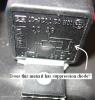
I didn't know that, I thought the fuse was to protect the device. ....and I didn't know that either. What does a relay with a suppression diode across the coil look like? Does what I did look OK? I know the Power from the battery to the relay is a little light but I will remedy that when I get some 40 amp wire. It is only running the GPS at the moment so it is not a problem yet. The signal is running of a 'key on' circuit so I shouldn't need a suppression diode relay should I? Thanks for the tips. It is really appreciated.
-
Thanks bhanks, where were you when I needed you. :icon_snooty: (gps install)
-
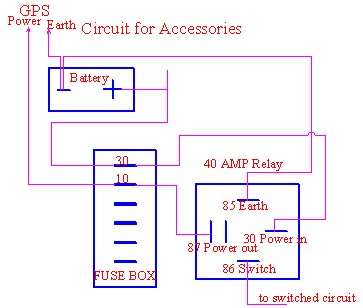
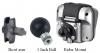
OK, I bought the TomTom Rider GPS and now I have installed it. The technical details are available on the Tomtom site so I won’t go into it here. The first problem was that a mounting part was left out of the kit. A quick trip back to the store and the problem was rectified. They were very good about it. Next problem: The kit has about 5 ways to mount the system, none of which work for the Bird. After much wailing and gnashing of teeth, and thinking, I had to make a custom mount. The mount is 25mm OD pipe with the end capped to weather proof it, and for looks. It is painted by dipping it in etch matt black. It is a little rough as it is only a proof of concept thing at this stage. I’ll make a better looking one later. It is bolted to the bar clamp using the standard bolt and is quiet rigid. It gives a good range of movement for visibility, clears all instruments and does not foul the tank in any direction. I think I’ll patent it. This is the bracket I had to make. It's a little rough because I didn't want to spend too much time on something I didn't know would work. Installed on bar clamp The pinch bracket needs has a ball on the GPS end so it can swivel. A rubber strip (too thick, I'll fix it) is used to stop movement between the bracket and mount. Finished view from rider point of view. Side view The power cable is routed from the GPS mount with the main loom down the left side of the bike (Some fairing removal needed) and held with cable ties. Next problem: I know very little about auto electrical work, so a quick call to this site yielded some very useful comments and suggestions. Getting power to the GPS seemed like a good time to add some upgrade capability to the system incase I add some more things later. So, a fuse box, a relay and a lot of fiddling around resulted in the system shown. Circuit diagram My real world interpretation of my diagram. The power is taken directly from the battery. The earth used is the one under the tank beside the rear tank mount. The relay signal is taken from white plug in the middle of the bank of relays. I unplugged it and removed the power side clip from the back of the plug and soldered the signal wire to the clip. The clip was then reinserted into the back of the plug. The plug fitted together as before. (I have no idea what the plug was for. I assumed the current draw would be small enough not to affect anything.) :icon_pray: Comment/Problems: *The wiring is not very neat and is only temporary. I’ll need to color strip the ends as the only heavy wire I had was black. I soldered, crimped and shrink wrapped everything mainly for practice for redoing it properly later. *The Relay is 40 amps but the main power wire is only rated at 20 amps, so the relay fuse is 20 amps. Upgrade later? Nah…I’ll wait until it starts blowing fuses. *The fuse box is a little tall and fits well….until I tried to put the seat on. :icon_doh: It had to be moved back a little. *Fuse box and relay is held in with double sided tape. When you stop looking at it, it lets go. Maybe hot melt glue? I don't like drilling holes in pristine plastics. *I need a better main power pick up. With my clip in place, the red silicone boot on the positive battery terminal won’t fit properly. *It worked first time. Relay, GPS everything, until I tried to put the seat on. (fixed) I hope this is of use to someone. Anything I have done wrong, let me know please. As I said, I know very little about auto electrics. Special thanks to Rockmeupto125. :icon_clap: Help was appreciated.
-
The antenna is integrated, and the unit unclips for removal. They provide a padded pouch to put it in. Actually they include everything. I can be used in the car also, with an exta mounting kit.
-
OK, I bought the TomTom Rider GPS and now I have installed it. The technical details are available on the Tomtom site so I won’t go into it here. The first problem was that a mounting part was left out of the kit. A quick trip back to the store and the problem was rectified. They were very good about it. Next problem: The kit has about 5 ways to mount the system, none of which work for the Bird. After much wailing and gnashing of teeth, and thinking, I had to make a custom mount. The mount is 25mm OD pipe with the end capped to weather proof it, and for looks. It is painted by dipping it in etch matt black. It is a little rough as it is only a proof of concept thing at this stage. I’ll make a better looking one later. It is bolted to the bar clamp using the standard bolt and is quiet rigid. It gives a good range of movement for visibility, clears all instruments and does not foul the tank in any direction. I think I’ll patent it. This is the bracket I had to make. It's a little rough because I didn't want to spend too much time on something I didn't know would work. Installed on bar clamp The pinch bracket needs has a ball on the GPS end so it can swivel. A rubber strip (too thick, I'll fix it) is used to stop movement between the bracket and mount. Finished view from rider point of view. Side view The power cable is routed from the GPS mount with the main loom down the left side of the bike (Some fairing removal needed) and held with cable ties. Next problem: I know very little about auto electrical work, so a quick call to this site yielded some very useful comments and suggestions. Getting power to the GPS seemed like a good time to add some upgrade capability to the system incase I add some more things later. So, a fuse box, a relay and a lot of fiddling around resulted in the system shown. Circuit diagram My real world interpretation of my diagram. The power is taken directly from the battery. The earth used is the one under the tank beside the rear tank mount. The relay signal is taken from white plug in the middle of the bank of relays. I unplugged it and removed the power side clip from the back of the plug and soldered the signal wire to the clip. The clip was then reinserted into the back of the plug. The plug fitted together as before. (I have no idea what the plug was for. I assumed the current draw would be small enough not to affect anything.) :icon_pray: Comment/Problems: *The wiring is not very neat and is only temporary. I’ll need to color strip the ends as the only heavy wire I had was black. I soldered, crimped and shrink wrapped everything mainly for practice for redoing it properly later. *The Relay is 40 amps but the main power wire is only rated at 20 amps, so the relay fuse is 20 amps. Upgrade later? Nah…I’ll wait until it starts blowing fuses. *The fuse box is a little tall and fits well….until I tried to put the seat on. :icon_doh: It had to be moved back a little. *Fuse box and relay is held in with double sided tape. When you stop looking at it, it lets go. Maybe hot melt glue? I don't like drilling holes in pristine plastics. *I need a better main power pick up. With my clip in place, the red silicone boot on the positive battery terminal won’t fit properly. *It worked first time. Relay, GPS everything, until I tried to put the seat on. (fixed) I hope this is of use to someone. Anything I have done wrong, let me know please. As I said, I know very little about auto electrics. Special thanks to Rockmeupto125. :icon_clap: Help was appreciated.
-
Thanks for the quick response. I was out of my depth there. I really appreciate the help. One more question though. What is the recommended method of patching into the tail light positive. A patch clip seems to be a rough way of doing it. Should I strip the wire near the tail light plug and solder a patch or...any other hints? At the tail light, or in the loom somewhere? BTW Ours are lights on all the time too.
-
[attachmentid=775] Hi Guys, I’ve bought a GPS and I need to start adding points to plug in accessories. I couldn’t find a power board similar to what was shown in here recently so I bought a fuse block instead. I am not too switched on with the electrical side of things. Could some of the electrical guys answer some questions for me? 1. Should I fuse the power going to the relay? 2. If the answer is yes, it’s a 40 amp relay, Do I use a 40 amp fuse or will a 30 be safer. (assuming total output is under 30 amps) 3. What rating fuse do you recommend for a GPS? 4. Where is a good point to patch into a switched circuit? From under the fuse block e.g. Headlight ? How much does a signal draw anyway? 5. If the attachment works, is the diagram correct? Any help greatly appreciated. :icon_pray:

-
The only thing I've ever heard is " Don't touch it, it doesn't need it and you will only make it worse. The things (throttle bodies) don't go out of adjustment on the Bird"