

mikesail
-
Posts
4,395 -
Joined
-
Last visited
-
Days Won
17
Content Type
Profiles
Forums
Gallery
Events
Everything posted by mikesail
-
Pretty typical problem of a missing ground connection. Your bike ECU is finding a ground path thru the light bulbs filament most likely, by applying power to the bulb you force the connection to become 12v instead of "ground". This is why it dies instantly. Make sure the ground connections from the ECU all the way to the chassis are good, I think that will solve it.
-
Here is my 2 cents..... If there is only varnish, and no rust, don't mess with it. The varnish will slowly dissolve in the fresh gas and be consumed with no problems. If you scrape it out by any mechanical method, you will have flakes of it getting into the filter or carb and possibly clogging or causing fuel flow issues. when a fuel system gets varnished heavily, it is really only a problem for small passages and valves, also the tank sender if you have one.
-
I have a few questions: Do you recommend putting dielectric grease in your connectors? Not normally, I prefer to keep them clean and visible for inspection, grease obscures your view. For something around salt spray, grease would be good to have. Does someone make a spray cleaner that you could follow with a spray protective grease for electric connectors? Lots of spray cleaners out there, but nothing that will take off corrosion like a file or sandpaper (or shall I say, coated abrasives) . I don't think that any cleaner would be incompatible with applying grease later. Is there a spray dielectric grease safe for low voltage ECU multi-pin connections? I have no knowledge of spray greases. However, there is nothing special about the ECU connections, the same considerations apply to all connections. The only relevant difference is that some ECU wiring is high impedance, meaning that a weak short or leakage, like from water, will effect the voltage on these circuits whereas the same leakage would not matter on any other normal circuits like ignition, lights, starter, alternator.
-
It really is very easy. The only issue is getting a stiff pin i.e. jewelers screwdriver or similar, into the opening past the terminal to release it. If you look into the open connector you can see the little tab that jams into the plastic. While pushing the wire back into the connector from the rear, you slide the screwdriver into the front of the connector until it gets past the tab, then simply pull the wire out and it is clear. To reinsert you simply push the terminal back in and the tab will lock again. comprende?
-
This post is a reply to the problem XXSIVSPD is having, but applies in general to connector issues. It is really a shame to lose a connector if you ever want to pull things apart later. It is true that a soldered connection is about as good a connection as you can make, but do you really want to lose the ability to unplug wires as originally intended? Remember that a connector is actually three connections in series. First is the wire crimped to one half of the connector, then comes the connector male to female joint, and third is the other wire crimp connection. Cleaning the male to female joint may let you miss the actual bad connection, it may well be that the crimp is bad. Typically the action of pulling on a poor connection will cause it to temporarily work again, so most likely you never really saw the bad connection. I'll bet that you have a bad crimp. For any crimp-on connection that I want to rely on, I prefer to solder the wire to the terminal right after it is crimped, then it will not ever pull out or lose connectivity because of corrosion. Most of these connectors will come apart with using a small jewelers screwdriver to release the locking tab. You can pull each connector "pin" out and visually check the crimp area, then solder as needed. The wire insulation will tend to get melted a bit, but if you are careful the melted part should be minimal and not extend past the connector body. Packing a connector with grease is ok after you know it is good, it will keep it free of corrosion. I prefer to put RTV in the connector around the wires where they exit to give a quick and cheap seal, it keeps them pretty clean and also gives the wire a bit of a strain relief. The connector Honda uses is adequate for carrying the electrical load, otherwise you would have problems on day one. If you can keep it clean and tight as it was when new,it will work indefinitely. Vibration and corrosion is what causes a crimp to fail over time, soldering will eliminate that concern. Dirt and corrosion are the cause of the terminals connection failure, sealing up the body will mostly prevent this from happening. Grease, tape, RTV are all viable ways to seal the terminals.
-
Please allow me to disagree, I think this is going in the wrong direction. I'm going to write up a new topic for this issue so more people can read it.
-
What was the problem that you found? Which wire is overheating? I'm not quite clear on that... BTW, I have the same kit and it has been flawless since installation. The problem was the wire on the starter button that goes to the headlights. When I first took the housing apart it looked like the solder just broke. So I resodered it. Before I put the housing back together I turned on the lights to make sure it was working and after about 30 seconds the wire popped back off. So I resoldered it again. This time when I turned on the lights I held my finger on the wire and I had to take my finger off because the wire was getting so hot. Then the solder let lose again. Is this clearer? Unfortunately, yes... There were no problems with the original lights right? Problem started when you installed the HID's, right? I'd try changing the low beam lead to the other ballast and see what happens. The solder is melting because of the combination of current flowing through the switch and the switch resistance. One or the other is too high. It is possible that the HID is consuming too much current, try using the original halogen bulb to check this possibility. If it still gets hot with the old light bulb, then the issue is simply a poor contact inside the switch, not at all uncommon. Most bike switches I've seen can be taken apart, and the contacts gently sanded until they are shiny clean copper again.
-
Hard to believe they are both bad. Almost certainly they are simple coils, if you can measure continuity they are probably fine. More to the point, if they were both bad the bike would not have the needed timing information to run in any fashion at all. Check all the chassis ground connections carefully, loosen inspect and re-tighten. Check fuel pressure.
-
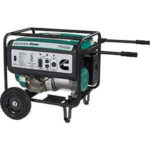
ative Power Systems | Portable Generators Cummins Onan HomeSite™ 5450e Portable Generator Enlarge < Previous Product | Next Product > Cummins Onan HomeSite™ 5450e Portable Generator Includes Wheel Kit Item # 365154 Be the first to write a review. Share this Product: Facebook Digg DelIcioUs Twitter $999.99 costco ad, there is a $200 discount till Sept 4th . Includes delivery. From another forum: >>>>> so I bought a new Cummins/Onan 5450E (5,000 watts continuous)model. Pretty much the same as the 6500. Did a FINE job indeed. The engine is actually a Honda with Cummins paint & sticky. Operated like a champ! 24hrs running & it burned only 10 gallons gasoline.
-
Are you saying that the relay chatters while you hold down the start button? If so, then either a bad battery or poor battery connection is most likely the culprit. Check both ends of both battery cables, loosen and retighten the connections. If the battery is weak, then jumping it will be the best test of that.
-

Track bike starter circuit, opinions/advice wanted...
mikesail replied to Redbird's topic in The Garage
The max output of the alternator is like 350 watts, or 350/12=30 amps or so. So you already know the total consumption is much less than that. As you've noted the big stuff has its own relays, I can tell you that your old bike runs with just a plug and socket for a kill switch and the current drawn is so low I can't even see a spark. So yes, its just a few amps at best, any switch you can operate by hand will be plenty stout enough. And you'll never be that guy who forget the key to his track bike -
Thanks, that is exactly what I finally figured it must be. We are good now, just need to get it recharged with the new hose.
-
yes, I've one of those on the LSR bike, this shock has no visible pin/detent/flat/slot etc.. Couldn't find my camera for some reason, so I looked over the shock once again. Thanks Stan, that got me the answer. The preload piston base is threaded, and locks with another lock ring. Just had to loosen the lock ring and then rotate the base as needed. it does change the preload by one turn, but then I've still got the whole range to move remotely. This whole exercise is to reorient and replace the hose to the remote valve, somehow I got the old one so hot the vinyl melted off the outside and the hose ruptured!!! I will be replacing it with a little better setup using AN fittings instead of the banjo's it came with. This will make it very easy to change the hose in the future to another length and/or add angle fittings as desired. Also the AN fittings have better flow than the banjo's so that might help fluid flow a bit, not heat the line so much.
-
Hopefully someone here has an answer for me. I would like to rotate the hydraulic preload piston on my Wilbers shock 180 degrees, so as to allow the remote damping valve port to face forward. I have the shock off the bike, and while it is possible to twist the spring around by hand, the preload adjuster seems to be fixed by means that are invisible. Does anyone here have any insight into how this unit is assembled and retained, and can it be rotated?
-
Not really if you have I4 engine with twin coiled waste spark system.Carburated bikes like that don`t need cam sensor. Pics in manual refers to lobes for cylinder 1,"driver" side.4 is "passenger" side. As long as Josh has T mark on ignition pulse generator rotor aligned properly with index mark on the cover cams and the trigger wheel are installed properly.Just look at the last set of pictures he has posted. I disagree, if you don't switch the coils then you will have spark every 1/2 crank rotation. This will cut into the coil energy storage at the very least. I understand that the carb version does not have this, but it is an improvement for the ignition to effectively operate at a lower rpm. Looking at the manual, it appears that there is a tick every 30 degrees for the ignition sensor. So it is clear that the ECU has to extrapolate between two marks to arrive at the actual timing. Without any other inputs, it seems that the carb bike must have had a different timing trigger wheel. .............. OK, just looked it up, the carb bike has missing teeth for orientation. Any chance an early trigger was put on? I think you said the pieces were from FI versions. Yea, it does look ok for engine timing. Totally agree here, good catch Hank
-
OK, that photo set does show all the complete cam sequence. Intake and exhaust and timing plate look correct. I assume that the crank timing is OK, hard to get that much off without jamming valves..... FPR?
-
Correct, and after looking more closely at the cam position trigger, you can see that there is 1 prong that is not 180 degrees off of the other, that's how it knows. So, we had the cams in the correct position in the first place. There is an electronic issue here -- crimped wire, bad connection, bad sensor, etc. The sensor on the crank is a hall effect sensor and those are VERY sensitive to contact, so even turning the crank backward or a slight bump might wreck it. Dean, you are missing what is happening for the cam trigger. Honda is doing something funny, a single pulse from the cam trigger is all you need for unambiguous timing. The extra two fingers are special for some unknown reason. If the exhaust cam is not set correctly on the cam sprocket (i.e. turned 180 ) , then the valves will still clear but you will have a really screwed engine with the exhaust opening at the same time as ignition occurs, more or less. Looking at the cam sprocket without seeing the lobes I cannot tell what the cam timing is. You need to turn the engine over and verify that the intake is opening just as the exhaust is closing, if not the cam is mismounted. You can check any cylinder, they will all be the same. If the cam sequence is correct, then it is necessary to check the phase of the cam trigger, since it is not symmetrical for some unknown reason. I think Stan was trying to say that the pic in the manual is misleading, need to know which lobe they are referring to. RPM is the ONLY factor that determines how often the injector valve opens, right? It absolutely does have sequential for fuel economy and driveability at a lower RPM with partial throttle positions. There is no other reason for a cam position sensor and the complexities it offers but the EPA does care about wasted fuel and emissions. Uh, there is another reason. Unless you have a distributor for the spark, you have to have a cam sensor to decide how to "distribute" the coil primary voltage. I agree, though it appears that the ECU will know if the trigger is inoperative.
-
A good starting point is to assume only one thing is wrong. It is of course possible that there are many faults. bit typically in this sort of case you just goofed up one thing. Since the gauges are showing problems when it first turns on, I have to believe that the ECU operation is at the root of your problem, not cams or valves. A single bad sensor should set you into limphome mode, your bike is much below that level. The air temp sensor would not cause the symptoms described. The best starting point is checking that you have good power and ground to the ECU harness. Did you reconnect the two green wires under the tank lip? After verifying that connection, I would use a test light, NOT a DVM, to verify that power AND ground are good at the ECU. A DVM can show voltage even when there is a poor connection, a light bulb will confirm the connection is sound enough to conduct the necessary current.
-
If you start the bike with the tank propped up, the hose is entirely visible. It is easy to see, and if your leak is there, as Tomek says you can get automotive hose ( special for EFI ) that will work fine.
-
The pump sealing surface is hopefully easy to check for flatness, using a straightedge. After eliminating that surface, check the tank for cracking in the sheet metal around the hole. I suspect the previous checks will show nothing, and the problem is likely then a subtle distortion of the sheet metal between the studs that mount the pump. If so, you might get away with using two gaskets stacked together, not normally a good idea but this is not a pressure application. Also look very closely at the studs to see if any have been tweaked, that would be the most likely way to distort the mounting flange area.
-
If the spacer tube is too short, as it would be if over-torqued at any time, your bearings will have a side load that they are not designed for, and they will undoubtedly fail sooner. With the bearing installed the tube should have very little play, as any clearance between the bearings and the spacer tube will cause side loading once the axle is torqued. A motorcycle shop mechanic once told me that he sees many bikes with bearing failures due to excessive tightening of the axle. The spacer tube is not strong at all. On the Bird the axle is retained by the fork clamps, the axle bolt is just to take out play in the system. It really needs very little torque to be set correctly.
-
Sounds to me like the bearing cup was not installed properly. I suspect it is not centered, and has moved when you hit a good bump. My bet is that the bearing is probably still fine, but you will need to take it all apart and correct the installation.
-
Are you guys pressure washing near the axles? The bearings should last much longer than your reports indicate.
-
http://www.turbocity.com/product_info.php?...products_id=573 Just one note to make. Turbo city is nearby, I've been there before and they have a very good reputation, at least in the turbo business. After talking to the owner on the phone about this FPR a while back, he believes that stock hondas are too lean, and thus his FPR's are set to increase the pressure a little, five percent if I recall right. Just keep in mind that his experience is with California bikes, your calibration might be fine with the stock unit.
-
My two cents. Guessing that you are hearing chain sounds. First guess is that your rear sprocket is not inline with the front, the chain will pop up a little if there is too much of an angle. Second thought is with your front sprocket, is it original with 48K on it? Could be a problem there.