

fizzy
-
Posts
1,044 -
Joined
-
Last visited
-
Days Won
1
Content Type
Profiles
Forums
Gallery
Events
Posts posted by fizzy
-
-
50 minutes ago, tomek said:
Nope. The text is perfectly fine and understable for someone who has a clue about basic physics. Not you obviously.
Anyway, I briefly considered another engine refreshment thread with new rings, some bearings, cylinder head rework and Kent camshafts. But I had my reservations after last couple of times when some clueless idiot did his best to ruin it. So, this was basically test run. And sure enough the very same guy made his presence felt again.
So, that thread won't happen, I don't have time to deal with that guy.
Btw, Swamp will be here shortly.
I agree with superhawk on the tone of that link. They compare their cam with the "original manufacturer" but don't say who or what that is. Also, don't say anything about power output, flow rates, etc.
Also they show what looks like valve bounce at 5000rpm on the original manufacturer and none on theirs. This means nothing, for all we know this original manufacturer cam may have a max speed of 4500rpm.
Edit: when designing and valvetrain, it is always good practice to keep the "jerk" to a minimum, if you know what that is. 😎
-
On 11/18/2022 at 6:59 PM, ptxyz said:
stock gearing. my apologies on the fpr update mistake. i was referring to the higher pressure for the 01-03 bikes (which mine is).
i should also mention all 3 of my birds ('97 jetted & full yoshi, '00 stock & my current '03 with yoshi slip ons) have had similar fuel economy.
If you can achieve 40mpg with "sedate" riding, then this is normal. If one of the sensors goes out of spec, I would expect a FI light ie an active code. You can also check for hidden codes, there is an unused 2 pin connector in the tail aft of the ECU. Bridge it with a paperclip to pull up all codes and to clear the system. See manual for details.
-
8 hours ago, ptxyz said:
25-30 mpg on my regular commute, with full throttle pulls getting onto the freeway, traffic permitting. low 40's when riding sedately in a group on the highways. been like this for several years.
been awhile since i checked the fpr, which i upgraded a few years back.
fan comes on around at around 220 degrees. know the part# for the ecu temp sensor?
" fpr, which i upgraded" upgraded?
-
1 hour ago, ptxyz said:
does the temperature sensor also feed information to the digital guage? in other words, there's only 1, correct?
apologies to the o.p. for piggybacking... my bird's always gotten horrible fuel mileage unless i'm riding like a granny...
Hopefully, bats62 returns with an update. In the meantime, how horrible?
Assume no dragging brakes, slipping clutch, silly rear sprocket, totally clogger air filter, etc. Check the FPR for a pinhole leak. Pull the vac line where it connects to the FPR after a brief (or long) start/stop. Vac line must be DRY.
Note: I think there are 2 temp sensors. One sends info to the ECU, this controls the fan. Other does the gauge (Digital dash model).
-
Could be a charging problem. What is the running voltage? Should be 13V (or a little more) at idle to 14.5V when revved.
-
16 hours ago, SwampNut said:
It's impressive with handheld tools. I work to a 64th but on highly precise stationary machines.
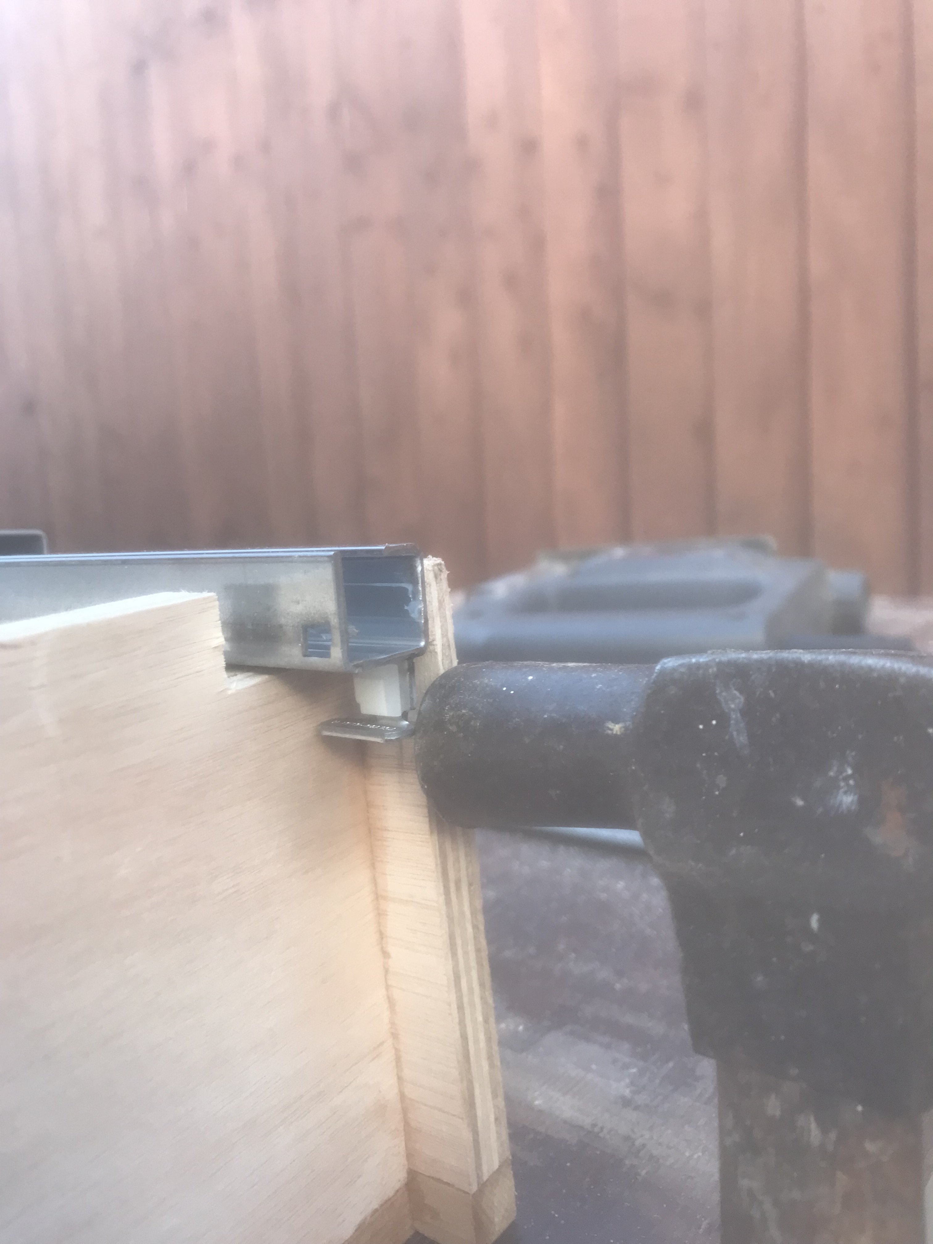
Not handheld tools. Everything was done on a table saw. A lightweight portable one. Takes longer and with more care to set up accurate cuts vs heavy shop saw, but results are almost as good. Only handheld tool was a jigsaw to cut out rear notch (see pic with hammer). Post was really to show that accurate and useful projects can be built with basic power tools. Thanks for looking.
-
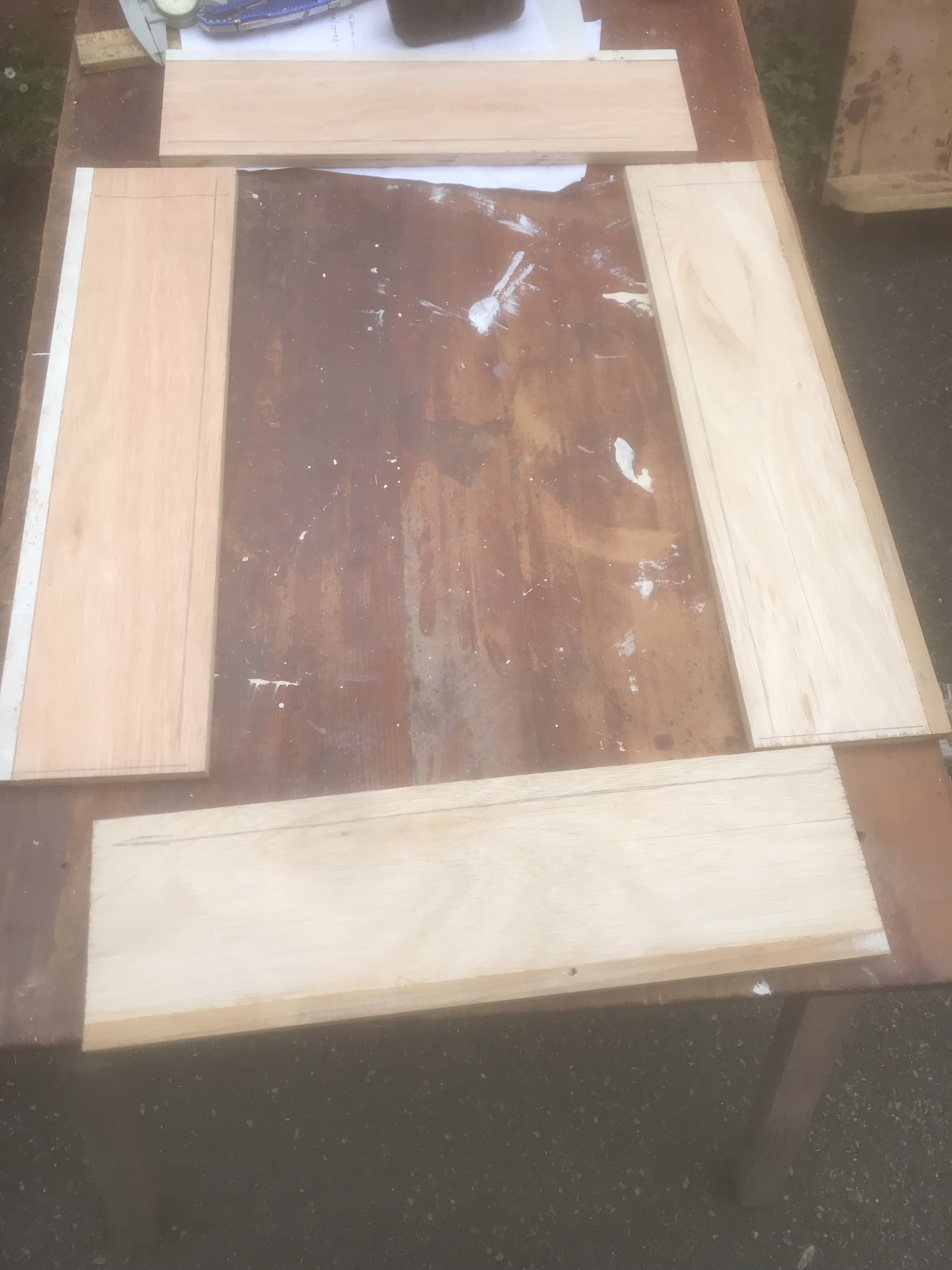
Kitchen is 25 years old, particle board construction. So not going to spend a lot of money on this. Also, you don't need fancy tools. Basic table saw, cordless drill, orbit sander, jig saw.
1. This part is almost not worth mentioning. Change the "euro style" hinges to soft close. Do not buy from the big box store. They are silly money. Bought online, 30 for £29.95. Only advice here is to make sure you get the exact right ones.
2. Install undermount soft close drawer guides. This requires brand new drawer boxes to work. Then mount the old drawer faces on the new drawer boxes. I used blum brand guides. These are not available at big box or local hardware store. If you live in a large enough town there may be a retail cabinet specialty store where this stuff can be purchased, along with advice to which style/size you need. Otherwise, order online and hope for the best. I messed up here and had to reorder. The blum brand is excellent quality, but there are no name brand eastern knockoffs for less money. They may be fine, who knows.
I had 4 drawers to make, so I purchased 1 sheet of 1/2" or 12mm cabinet ply. I used this for the sides and the base. With this type of drawer guide, the box must be made width and depth to within 1/16" or better. In order to figure out what these dimensions are, there are a few things you must do.
1. Throw away the instructions. This is important for your mental health and the safety of those around you.
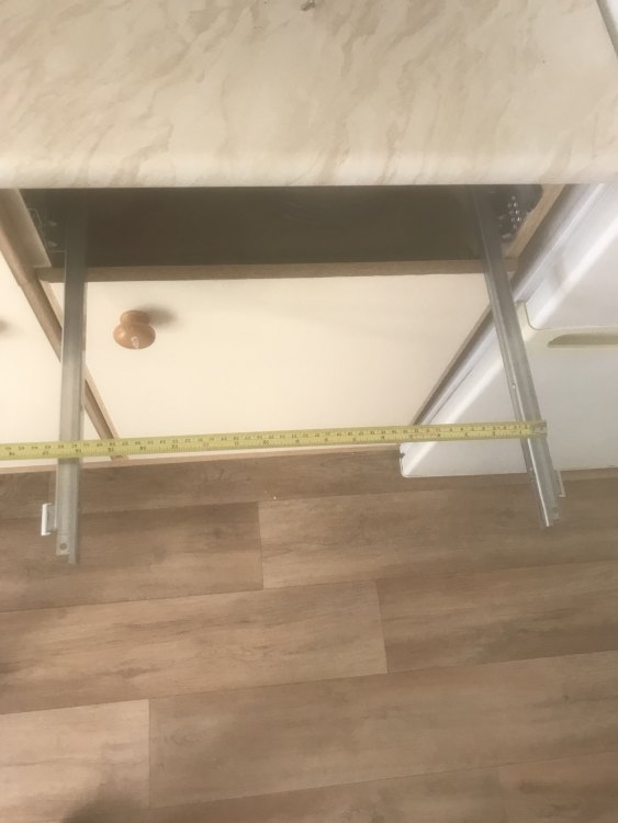
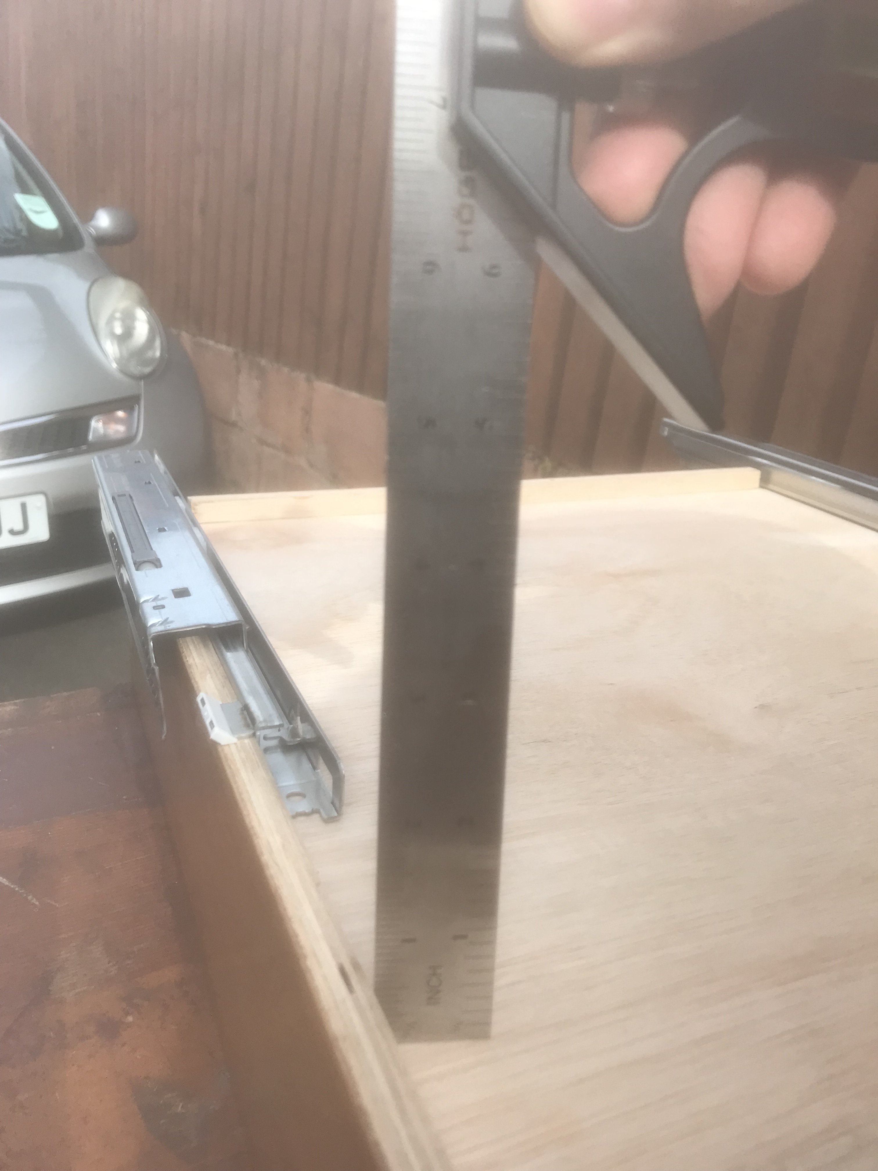
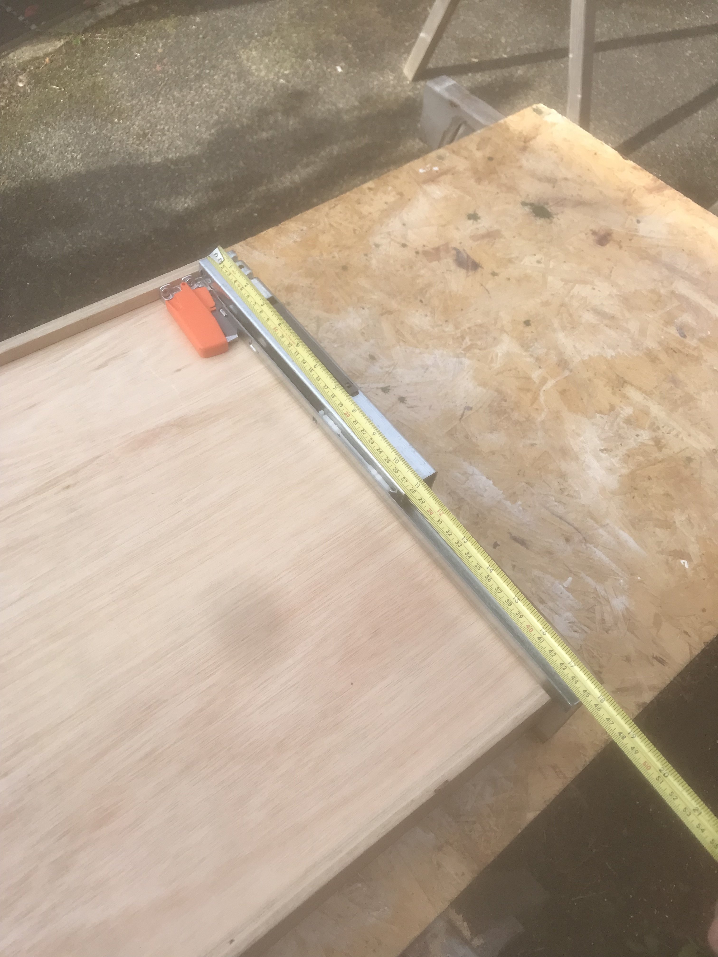
2. Width measurement: mount the guides in the cabinet, pull out the moving part of the guides and measure outside to outside....see pic. Add 1/16". This is the inside to inside measurement of the width of the drawer box.
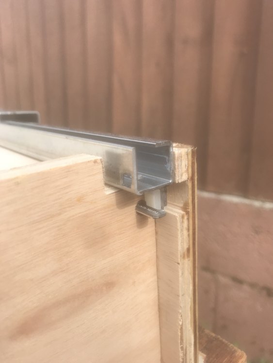
3. Depth measurement: Click orange clip onto guide. Measure end of orange clip to base of rear pin. This is inside to outside measurement of depth of drawer box. See pic with hammer. It shows me marking the small hole to be drilled for this pin.
4. Bottom of drawer box to underside of base MUST be 1/2" or 12mm.
I bought the cheapest blum unit 3/4 extension (not full) and only adjustment up/down on the face. Can spend more and get more adjustability. £11/drawer vs £39+.
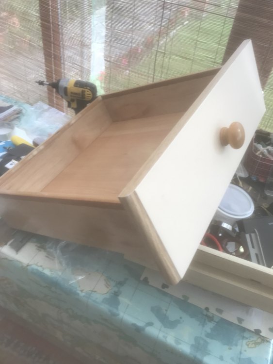
Box construction, simple 1/2" wide rabbits x 1/4" deep, screwed and glued. Pocket screws would be fine too. Bases cut 1/16" smaller the rabbeted recess they live in, this makes/keeps the box square.


-
 1
1
-
 1
1
-
-
It is good practice to connect the output from the R/R directly to the battery + and -. Use an inline 30A fuse on the + side. This eliminates the loom from this circuit. I am sure I don't have to explain why this is a good idea.
Also, recommend to mount a small voltmeter to the dash, anything over 14.5V, head home at 1200rpm.
PS: Tape off the unused connector (when you wire direct to battery) and you are done.
-
Got it running, good job. One more blackbird back on the road and that is a good thing.
15.6V at idle, agreed, new R/R is needed.
Get this one Home (roadstercycle.com) . this is a genuine mosfet unit, FHA020AA superkit with wiring to connect straight to the battery.
-
1
-
1
-
-
9 hours ago, Furbird said:
I don't think we were clear, or if you watched the video or not, but you actually have to unplug the block and check the inside to verify there is no corrosion on that ground and power test connectors. I'd be shocked on a 22 year old bike if it doesn't have some corrosion in it. Not doubting you, just saying historically speaking that is very rare.
Also re-read the previous and it popped a 30 amp fuse which means you had a dead short in the ECM (or perhaps somewhere else in the wiring that also fried the ECM.)
Over the years I have added an additional battery to engine and battery to frame ground separate from the factory connections. Just something I've always done as a carryover from my years in car audio installs because the factory stuff was always so lackluster. If somebody has been in there digging around they may have left something unbolted and you may have missed it. There's one ground right by the battery where the left tank bolt is (I believe that's right, off the top of my head) you might want to check and make sure that's there or not loose."Also re-read the previous and it popped a 30 amp fuse which means you had a dead short in the ECM (or perhaps somewhere else in the wiring that also fried the ECM.)"...................Agreed, dead short in the wiring probably as the ECM can only provide a ground at the end of the road. Trying to see how that could trip a fuse, especially a 30A fuse as the ECM wires are not designed to carry that much current.
"Over the years I have added an additional battery to engine and battery to frame ground separate from the factory connections. "....................On my machine I added 2 extra grounds, one from the one fat green wire during the loom fix and the second from the low beam ground wire 2" from the headlight.
-
7 hours ago, JJMills1993 said:
It is surprisingly clean but I am still going to perform the loom fix. I have two “plugs” they appear to be used as a bus bar one for positive and negative connections. There is continuity between all wires in the ground distribution when back probed with the cap on.
" I have two “plugs” they appear to be used as a bus bar one for positive and negative connections." Not sure what that means
"There is continuity between all wires in the ground distribution when back probed with the cap on. " That may be so but is not the whole story. Look carefully inside the cap and check the bus bar. It is not continuous. Honda in its wisdom broke this bar into sections. The solder job should match this exactly. If memory serves there were 4 altogether.
-
1 hour ago, Furbird said:
The real question is do you want to keep chasing this ghost or just make it so the bike will run? If all it is is this one thing, you might consider putting up the proton pack and parking Ecto 1 and just wiring up the fuel pump directly to bypass this Ghostbusters mission.
Yes, do this first.
In other words, hotwire the pump, see if she runs. Then troubleshoot.
-
Pull the pump relay and the connector at the pump. Hotwire the pump + and -. See if the bike runs and if there are FI codes.
If it runs, there is something amiss with the pump relay circuit
Not quite sure what you mean by polarity of the relay. You say you already tested them. Wouldn't that have been apparent during the test?
-
Unless it is PRISTINE then do the "loom fix". Cut the wires and solder together in the exact same manner they are now connected. Remove the cap and inspect the bus bar, it should make sense once you see it is not 1 piece.
Pop the 30A PGM-FI fuse? 30A fuse is for the start/stop function. You might have a pinched/broken wire hidden somewhere. You also may well have 2 functioning ECUs, or none. Hard to say at this point.
Check the small wires into the 2 multi pin ECU connectors. If the ECU is not strapped down, it will move and can eventually invisibly damage these wires near the connector.
Make certain of a good ground to the fuel pump. If in doubt, add a second one. Note, this pump ground may be the original culprit, even shorting out another wire in the loom.......possibly eliminate it altogether.
-
1
-
-
As furbird states above, there is a test plug or junction block probably brown in color buried under tape in the main loom near where it passes by the battery. Visible as a small square shape outlined thru the tape. This junction is mostly ground wires separated into 3 + some colored wires. As stated, they corrode and you lose ground.
Cut the tape away to check.
-
5 hours ago, SwampNut said:
LOL, again, don't feed the troll. You can't tell fuck-all from a dark picture of black leather taken at 90 on an old 2MP digital camera. On the tenth or more run of the same corner trying every possible angle to improve it on each run.
I'm just already dead and don't know it.
When a joke comes across my desk, my mission is to crack it. Once in a while, one will stick to someone's funny bone. It's as simple as that.
I know you tried and failed to give me advice, thanks for trying. Now its my turn
"Not necessary to explain yourself."
Quote: Never explain, never complain. Henry Ford
-
1 hour ago, tomek said:
If I had to explain to you would not understand.
That kind of body position is dominating in Novice class. I mean it is ok to ride like that at moderate pace but when pushing hard you are asking for the front to close up.
Back to the subject, I would not de-link for any street riding.
Linked brakes will become an issue during very aggressive braking before corner entry (wheel hop, etc), but that kind of riding should be reserved for race track anyway.
"If I had to explain to you would not understand." tomek
“If you can't explain it to a six year old, you don't understand it yourself.” ― Albert Einstein.-
1
-
-
22 minutes ago, tomek said:
Absolutely horrible novice-like body position, I'm shocked you are still alive.
Is that because he's leaning to the right?
-
2
-
-
You might want to double check this, but I believe the fairing stay for carb bird is different to FI.
-
On 4/16/2022 at 1:52 PM, superhawk996 said:
I know what made it coil, the manufacturer, what we won't know is what it takes to un-coil.
Talk to this guy.
-
1
-
1
-
-
Sounds like Swampnut needs a swamp cooler?
-
1
-
-
If it is in the budget, you should look at LED headlights. Good ones are more compatible with the reflectors in the bird shell than HID + they are instant on.
-
Ballast? What aftermarket bulbs are you using as the bird does not come with ballasts as stock?
Anyway, try a spray electrical cleaner into the switch as a first go.
What is your running voltage?
-
After coat 47 didn't work, you went ahead with 10 more?🍺
Your first pic showed areas of differing gloss. Anyway, I'm not there, you are. These things don't always show up well on pics. I think you are expecting too much from Behr, as it is low grade bottom shelf stuff.
If you don't like my advice, go to a pro paint store, follow their advice and buy only top grade paint, at least for this particular project.


Titanium vs. Stainless Steel
in The Garage
Posted
You are missing our point, again. We or you, don't know what engine they are comparing to, which is why their claims of greatness are suspect.
Can I presume you don't know the meaning of my reference to "jerk"?