

JJMills1993
-
Posts
12 -
Joined
-
Last visited
Content Type
Profiles
Forums
Gallery
Events
Posts posted by JJMills1993
-
-
2 hours ago, Furbird said:
40 man hours at shop rate = totaled. 40 man hours at your time = helluva deal.
That must be low miles and lived inside to be that clean. The connectors anyway.yeah this is what I do everyday. I spent more hours with a multimeter in my hand then anything else with this bike. Checking and double checking.
Was laid down at some point and shows it. Got it drivable, threw a battery in it and two new head lights. Popped both bulbs as soon as I went above idle. Showing 15.6 volts at idle….
guess I’ll need a regulator/rectifier too
odometer shows 22k. Speedo isn’t working so not sure how accurate that is. Colorado bike so lives inside for 8 months a year. That coupled with how dry it is here.
-
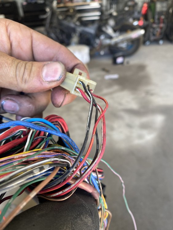
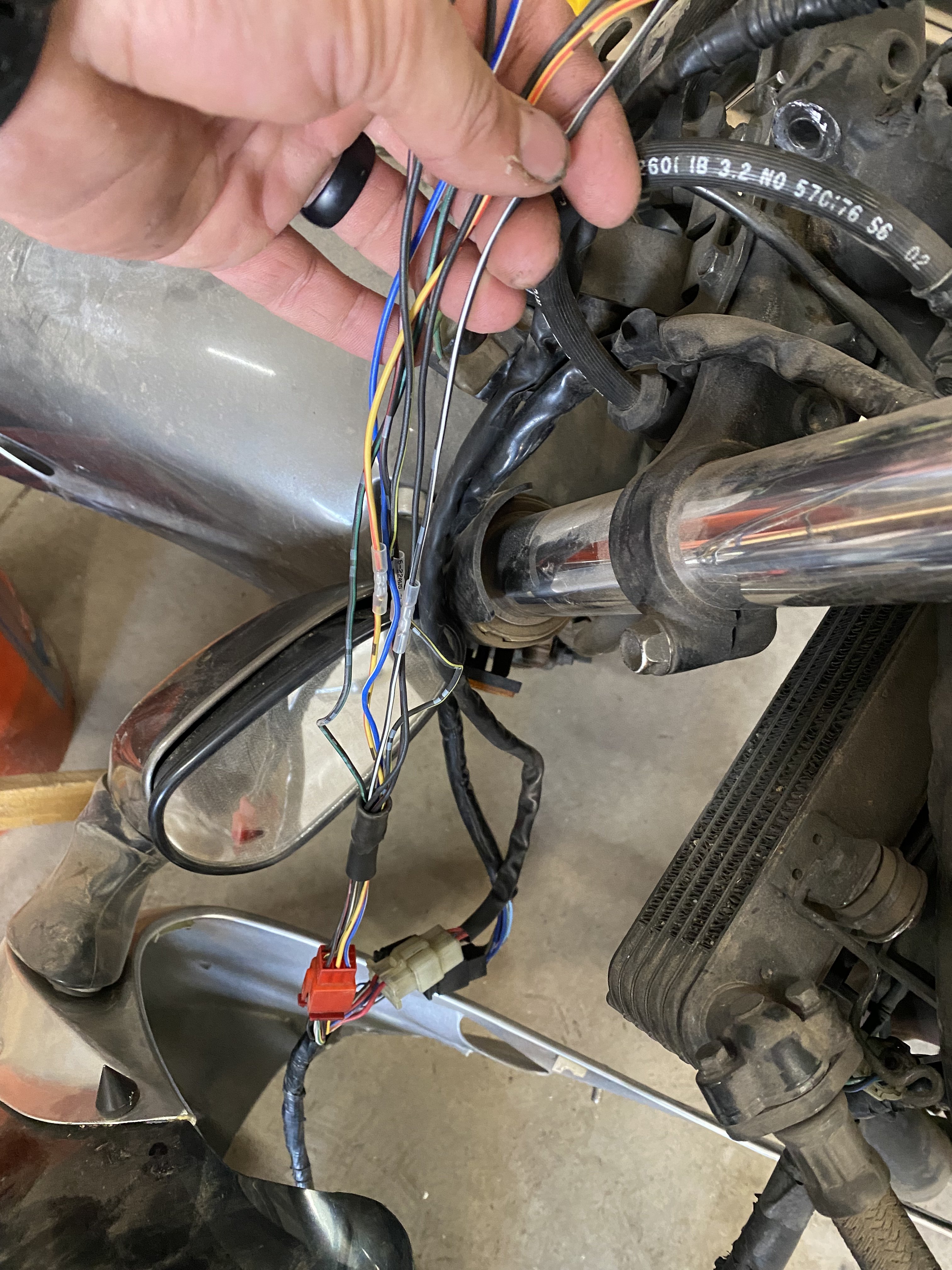
Well I was able to get the harness buttoned back up today. Also found another harness issue after and was able to confirm that the bank angle sensor. (New one from used harness and old one were bad). “Hot” wired the bank angle sensor and confirmed voltage at the fuel pump. Also had 4 wires melted together in the right hand control harness. What’s crazy is it tested good continuity through kill switch circuit when on, and none when off.
This bike had a broken nose faring support that was the original problem until I went and looked at it. For $300 and 40 man hours I’m not going to complain.
After repairing sub harness and reconnecting everything it fired right up. Been sitting since 2020.
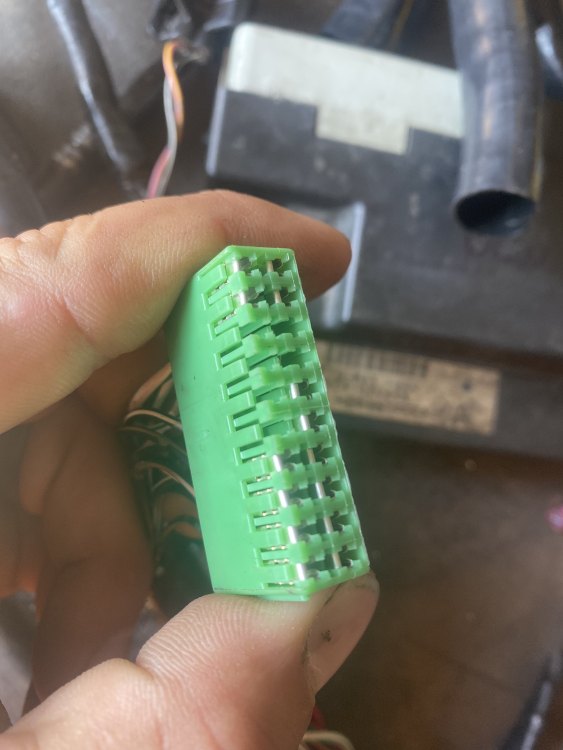
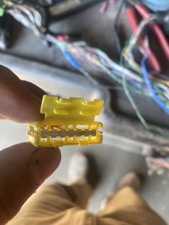
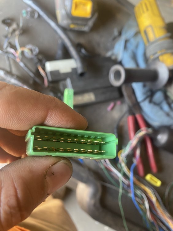
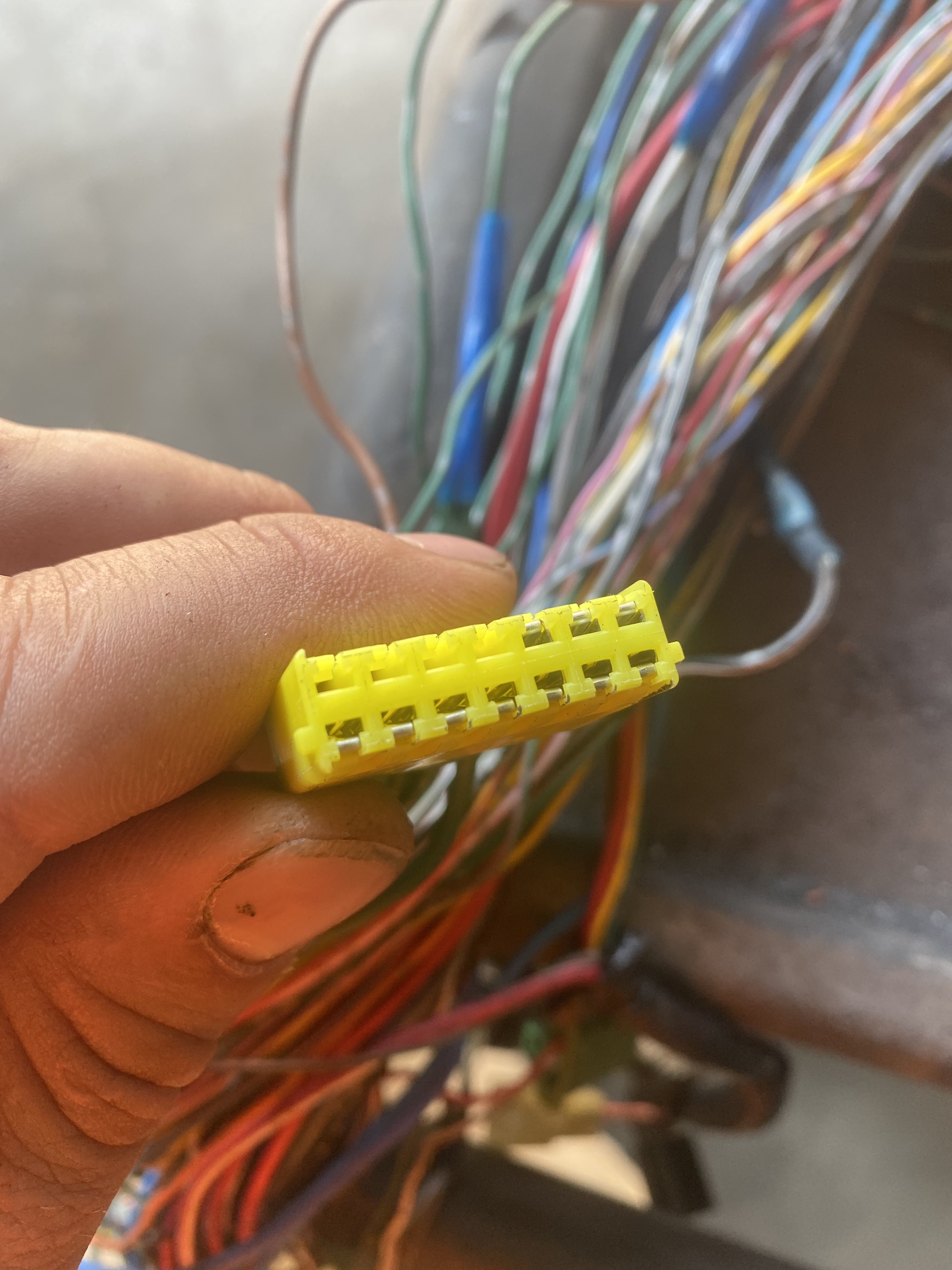
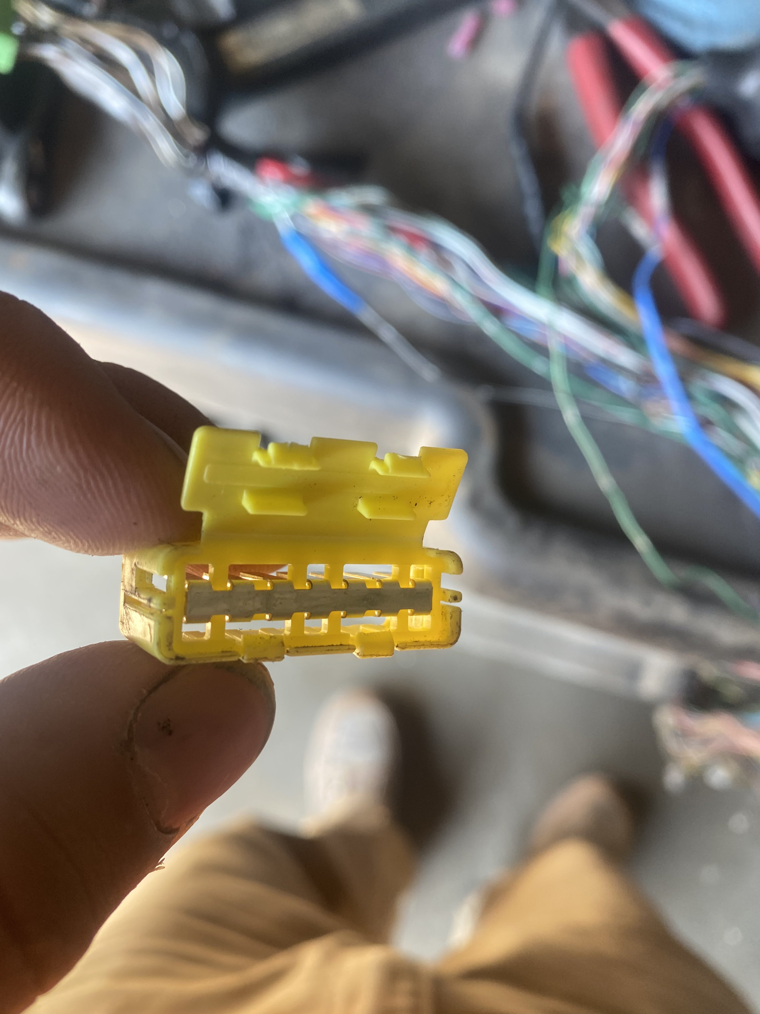
As for the loom fix. It is immaculate. Both the negative and positive. The yellow is my ground block that is all interconnected as show in pictures.
The green was my positive with 4 separate groups connected like Fizzy and Furbird said.


-
 1
1
-
-
1 hour ago, Furbird said:
I don't think we were clear, or if you watched the video or not, but you actually have to unplug the block and check the inside to verify there is no corrosion on that ground and power test connectors. I'd be shocked on a 22 year old bike if it doesn't have some corrosion in it. Not doubting you, just saying historically speaking that is very rare.
Also re-read the previous and it popped a 30 amp fuse which means you had a dead short in the ECM (or perhaps somewhere else in the wiring that also fried the ECM.)
Over the years I have added an additional battery to engine and battery to frame ground separate from the factory connections. Just something I've always done as a carryover from my years in car audio installs because the factory stuff was always so lackluster. If somebody has been in there digging around they may have left something unbolted and you may have missed it. There's one ground right by the battery where the left tank bolt is (I believe that's right, off the top of my head) you might want to check and make sure that's there or not loose.It is surprisingly clean but I am still going to perform the loom fix. I have two “plugs” they appear to be used as a bus bar one for positive and negative connections. There is continuity between all wires in the ground distribution when back probed with the cap on.
There was a dead short in the Ecm. After it popping the fuse (6 times for proof of concept) I ordered another one off ebay. It no longer pops the fuse.
I have removed and cleaned the frame where that ground is bolted In. Even sanded off some surrounding paint to
ensure a good ground.
-
37 minutes ago, superhawk996 said:
If you meant PGM-FI fuse instead of relay, you appear to be correct.
Yes sorry fuse not relay.
27 minutes ago, fizzy said:Yes, do this first.
In other words, hotwire the pump, see if she runs. Then troubleshoot.
Let the hot wiring begin.
-
20 hours ago, XXitanium said:
The test loom is all grounding.
The repair is soldering the wire ends into a lump.
This link below is a great resource. There are a couple pictures added back in.
It looks like you are very handy with electrics.
I will give this a try
-
5 hours ago, jon haney said:
Don't think polarity matters on a single-pole, single-throw relay. It certainly doesn't on the switch terminals.
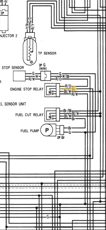
Looking at the diagrams above, the fuel-cut relay, or what powers it is the problem. The engine stop relay doesn't appear to provide power or ground for the fuel-cut relay. Good luck.
The bl/w wire gives power to fuel relay, injectors, PCM and a few others. It receives that power from the engine stop relay being energized and connecting the bl/w to the R/W that comes directly from the PGM-FI relay. At least that’s how I read it, is that incorrect?
-
12 hours ago, fizzy said:
Pull the pump relay and the connector at the pump. Hotwire the pump + and -. See if the bike runs and if there are FI codes.
If it runs, there is something amiss with the pump relay circuit
Not quite sure what you mean by polarity of the relay. You say you already tested them. Wouldn't that have been apparent during the test?
Polarity of that wire. It has been tested and should be a ground but I don’t have the ground there to energize the relay
-
6 hours ago, fizzy said:
Unless it is PRISTINE then do the "loom fix". Cut the wires and solder together in the exact same manner they are now connected. Remove the cap and inspect the bus bar, it should make sense once you see it is not 1 piece.
Pop the 30A PGM-FI fuse? 30A fuse is for the start/stop function. You might have a pinched/broken wire hidden somewhere. You also may well have 2 functioning ECUs, or none. Hard to say at this point.
Check the small wires into the 2 multi pin ECU connectors. If the ECU is not strapped down, it will move and can eventually invisibly damage these wires near the connector.
Make certain of a good ground to the fuel pump. If in doubt, add a second one. Note, this pump ground may be the original culprit, even shorting out another wire in the loom.......possibly eliminate it altogether.
I’m not getting power to the pump because it is not making it through the relay but the relays have tested good. There are two 30amp fuses on my bike. The 30amp at the starter solenoid and another single thirty amp that is not in the main fuse block that runs directly to the engine stop relay.
If someone with the same 99-2000 model knows or could pop this relay and tell me me the polarity that would help me greatly.
-
15 minutes ago, fizzy said:
As furbird states above, there is a test plug or junction block probably brown in color buried under tape in the main loom near where it passes by the battery. Visible as a small square shape outlined thru the tape. This junction is mostly ground wires separated into 3 + some colored wires. As stated, they corrode and you lose ground.
Cut the tape away to check.
I have stripped all the tape away and believe I found the junction you are referring to. It is clean and dry. No corrosion.
-
31 minutes ago, Furbird said:
00's have the same plug as the 99's have, which is the test plug under the battery. Known issue. Should be electrical taped to the main wiring harness, known for getting water intrusion and corroding the wiring. One of my bikes got both the power AND ground test plugs to the point I had to replace entire sections of wiring from end-to-end.
Not sure which plug you are referring to when you say test plug. I have the harness out and stripped. Im Not seeing any signs of corrosion currently
-
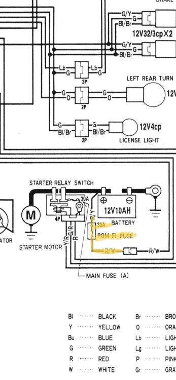
I’ve been scouring this forum and others for the last few weeks trying to find an answer to my current problem
I bought a 2000 model year 1100XX
with a known electrical issue.
No fuel pump cycle upon turning key and handlebar switch on.
I immediately tore it apart to find out somebody had tried to take power from somewhere else and feed pump. The harness was subsequently melted in multiple places. Supply ground for PGM-FI computer. +12v black white wire which comes off the main power supply distribution to the grey ECU connector. I tore the harness apart removed and replaced all burned/exposed electrical wires.
Reassembled only to find out that with the ECU plugged in when the key was turned on it would immediately pop the 30amp PGM-FI fuse. With the ECU unplugged no issue. I got my hands on a used ECU from eBay. Plugged it in and it no longer blows the 30amp PGM-FI fuse. I still do not have power to the fuel pump and I believe it to be a ground issue but need some expertise to help guide me here.
I have traced and have power through the electrical connections I should until I get to the engine stop relay. I have Voltage and continuity tested ignition and handlebar switch. The power that comes into the engine stop sensor is good. It comes in and out of the tip over sensor under the seat. I do not have a ground to cycle the engine stop relay and can’t pinpoint the issue. I have bench tested the relays all good. Does the ecm provide a ground? Is my new to me ECM bad? The diagram reads I should have 12v at the Bl/W wire at that relay to feed the fuel pump relay. Power is there just not getting from the R/W main power wire through the known good relays to provide power to fuel pump relay. Harness is back off the bike and stripped down to re-Inspect but I haven’t found any connection issues this time.
Sorry for the long winded write up. Just looking for someone with more electrical theory education than I have.


2000 Model year XX electrical diagnosis
in The Garage
Posted
I already ordered the new regulator last night. If that one’s doesn’t work out for any reason I’ll give those a try
Hopefully there hasn’t been any more damage to the electrical system then just the two blown headlights. I need to start diagnosing the speedo and tach next.